Run Commands in computer.
• appwiz.cpl -- Used to run Add/Remove wizard
• Calc --Calculator
• Cfgwiz32 --ISDN Configuration Wizard
• Charmap --Character Map
• Chkdisk --Repair damaged files
• Cleanmgr --Cleans up hard drives
• Clipbrd --Windows Clipboard viewer
• Control --Displays Control Panel
• Cmd --Opens a new Command Window
• Control mouse --Used to control mouse properties
• Dcomcnfg --DCOM user security
• Debug --Assembly language programming tool
• Defrag --Defragmentation tool
• Drwatson --Records programs crash & snapshots
• Dxdiag --DirectX Diagnostic Utility
• Explorer --Windows Explorer
• Fontview --Graphical font viewer
• Fsmgmt.msc -- Used to open shared folders
• Firewall.cpl -- Used to configure windows firewall
• Ftp -ftp.exe program
• Hostname --Returns Computer's name
• Hdwwiz.cpl -- Used to run Add Hardware wizard
• Ipconfig --Displays IP configuration for all network adapters
• Logoff -- Used to logoff the computer
• MMC --Microsoft Management Console
• Msconfig --Configuration to edit startup files
• Mstsc -- Used to access remote desktop
• Mrc -- Malicious Software Removal Tool
• Msinfo32 --Microsoft System Information Utility
• Nbtstat --Displays stats and current connections using NetBIOS over TCP/IP
• Netstat --Displays all active network connections
• Nslookup--Returns your local DNS server • Osk ---Used to access on screen keyboard
• Perfmon.msc -- Used to configure the performance of Monitor.
• Ping --Sends data to a specified host/IP
• Powercfg.cpl -- Used to configure power option
• Regedit --Registry Editor
• Regwiz -- Registration wizard
• Sfc /scannow -- System File Checker • Sndrec32 --Sound Recorder
• Shutdown -- Used to shutdown the windows
• Spider -- Used to open spider solitaire card game
• Sfc / scannow -- Used to run system file checker utility.
• Sndvol32 --Volume control for soundcard
• Sysedit -- Edit system startup files
• Taskmgr --Task manager
• Telephon.cpl -- Used to configure modem options.
• Telnet --Telnet program
• Tracert --Traces and displays all paths required to reach an internet host
• Winchat -- Used to chat with Microsoft
• Wmplayer -- Used to run Windows Media player
• Wab -- Used to open Windows address Book.
• WinWord -- Used to open Microsoft word
• Winipcfg --Displays IP configuration
• Winver -- Used to check Windows Version
• Wupdmgr --Takes you to Microsoft Windows Update
• Write -- Used to open WordPad
Showing posts with label Basic Computers. Show all posts
Showing posts with label Basic Computers. Show all posts
Tuesday, August 11, 2009

How to restrict user's to access shutdown button?
How to restrict user's to access shutdown button?
Solution: This tip is very interesting for home and some small office users, who wants to restrict user's ability to shutdown their computer. You can hide the Shutdown button from the Start menu using registry editor and also restrict access to shutdown, if a user clicks on Ctrl+Alt+Del.
Follow the given steps to hide system shutdown button from start menu:
• To use this feature, you will need to be logged into your computer with
administrative rights.
* Click Start button and type regedit in Run option then press Enter for next.
* Here locate the location to:
* HKEY_CURRENT_USER\Software\Microsoft\Windows\CurrentVersion \Policies\Explorer
* Here in right side panel, right click to create a new DWORD value with name NoClose.
* Now assign number 1 to its value data box.
* Now close the registry editor and restart your computer after any changes to go into effect.
* But next time, if you want to unhide the shutdown button then simply change the value data box to 0 or delete this DWORD item.
* Again close the registry editor and restart your computer after any changes to go into effect.
Solution: This tip is very interesting for home and some small office users, who wants to restrict user's ability to shutdown their computer. You can hide the Shutdown button from the Start menu using registry editor and also restrict access to shutdown, if a user clicks on Ctrl+Alt+Del.
Follow the given steps to hide system shutdown button from start menu:
• To use this feature, you will need to be logged into your computer with
administrative rights.
* Click Start button and type regedit in Run option then press Enter for next.
* Here locate the location to:
* HKEY_CURRENT_USER\Software\Microsoft\Windows\CurrentVersion \Policies\Explorer
* Here in right side panel, right click to create a new DWORD value with name NoClose.
* Now assign number 1 to its value data box.
* Now close the registry editor and restart your computer after any changes to go into effect.
* But next time, if you want to unhide the shutdown button then simply change the value data box to 0 or delete this DWORD item.
* Again close the registry editor and restart your computer after any changes to go into effect.
How to add Items to the Start Button using Registry in Computer
How to add Items to the Start Button using Registry in Computer
Solution: The best technique to edit the windows registry keys, always export or backup the whole windows registry keys on backup drive before editing. Because any mistake in Registry can cause serious problem in your computer to run properly.Follow the given steps to change the Start button setting.First click on Start button then type Regedit in Run option.In Registry Editor go to left hand panel, and find HKey_Classes_Root / Directory / Shell Here Right click on Shell folder option and add any new key with descriptive name and Press Enter.
Now Right click on that key and give the full path of that program you are interested to add in start button. For example if you want to add MS excel, then full path may beC:\program file\msoffice\msexcel.EXE.Now close all open programs and check the changes in your computer Start button.
Solution: The best technique to edit the windows registry keys, always export or backup the whole windows registry keys on backup drive before editing. Because any mistake in Registry can cause serious problem in your computer to run properly.Follow the given steps to change the Start button setting.First click on Start button then type Regedit in Run option.In Registry Editor go to left hand panel, and find HKey_Classes_Root / Directory / Shell Here Right click on Shell folder option and add any new key with descriptive name and Press Enter.
Now Right click on that key and give the full path of that program you are interested to add in start button. For example if you want to add MS excel, then full path may beC:\program file\msoffice\msexcel.EXE.Now close all open programs and check the changes in your computer Start button.
Clearing the Documents History Automatically
Clearing the Documents History Automatically
The windows Documents Menu display all the information about last used files and programs as a history. Your co-workers, family members can trace your activates on the computer with clicking on Documents menu. If you are using internet at any public place like internet cafe then you should clear your documents menu history to safe yourself from cyber crimes. You can clear the documents menu history manually, but automatically history clean option can be useful if one computer used by multiple people. To clear the document history automatically, edit the computer registry keys.
Click Start button then type regedit in Run option then press Enter for next.Here locate the location to:
Go to HKey_Current_User \ Software \ Microsoft \ Windows \ CurrentVersion \ Explorer \ User Shell Folders Here in right side panel, double click on Recent and change its value of C:\RECYCLED. Now set your Recycle bin, "remove files immediately when deleted". Now close the registry editor and restart your computer after any changes to go into effect.
The windows Documents Menu display all the information about last used files and programs as a history. Your co-workers, family members can trace your activates on the computer with clicking on Documents menu. If you are using internet at any public place like internet cafe then you should clear your documents menu history to safe yourself from cyber crimes. You can clear the documents menu history manually, but automatically history clean option can be useful if one computer used by multiple people. To clear the document history automatically, edit the computer registry keys.
Click Start button then type regedit in Run option then press Enter for next.Here locate the location to:
Go to HKey_Current_User \ Software \ Microsoft \ Windows \ CurrentVersion \ Explorer \ User Shell Folders Here in right side panel, double click on Recent and change its value of C:\RECYCLED. Now set your Recycle bin, "remove files immediately when deleted". Now close the registry editor and restart your computer after any changes to go into effect.
Disable drives in My Computer from unknown user
Disable drives in My Computer from unknown user
If you want to prevent any users to access your computer or network shared drives using My Computer then you can hide the all drives for example C:/, D:/ and save your data from any unknown user. But next time you can turn on the display of these drives using registry editor. Now edit the computer registry to turn off the display of drives, but be careful to work with computer registry.
Follow the given steps to hide computer drives:First click on Start button then type Regedit in Run option.Here locate the location to:
Key_Current_User \ Software \ Microsoft \ Windows \ Current Version \ Policies \ Explorer Here right click on right side of Registry editor panel and add new DWORD then put its value 3FFFFFF.
Now close the registry editor and restart your computer after any changes to go into effect.
If you want to prevent any users to access your computer or network shared drives using My Computer then you can hide the all drives for example C:/, D:/ and save your data from any unknown user. But next time you can turn on the display of these drives using registry editor. Now edit the computer registry to turn off the display of drives, but be careful to work with computer registry.
Follow the given steps to hide computer drives:First click on Start button then type Regedit in Run option.Here locate the location to:
Key_Current_User \ Software \ Microsoft \ Windows \ Current Version \ Policies \ Explorer Here right click on right side of Registry editor panel and add new DWORD then put its value 3FFFFFF.
Now close the registry editor and restart your computer after any changes to go into effect.
Hide the Desktop Icons
Hide the Desktop Icons
Solution: You can hide the Desktop Icons in Windows 2000 and Windows XP using windows registry editor. This tip is very useful, if you want to safe your personal data and icons of the windows desktop on a single computer. Follow the given steps to to hide Desktop Icons:Click Start button then type regedit in Run option then press Enter for next. Here locate the location to: HKEY_CURRENT_USER\Software\Microsoft\Windows\CurrentVersion\Policies\Explorer Here in right side panel, right click to create a new DWORD value with name NoDesktop and type REG_DWORD then change its value data 1.
Now close the registry editor and restart your computer after any changes to go into effect.
Solution: You can hide the Desktop Icons in Windows 2000 and Windows XP using windows registry editor. This tip is very useful, if you want to safe your personal data and icons of the windows desktop on a single computer. Follow the given steps to to hide Desktop Icons:Click Start button then type regedit in Run option then press Enter for next. Here locate the location to: HKEY_CURRENT_USER\Software\Microsoft\Windows\CurrentVersion\Policies\Explorer Here in right side panel, right click to create a new DWORD value with name NoDesktop and type REG_DWORD then change its value data 1.
Now close the registry editor and restart your computer after any changes to go into effect.
How to fixing no AutoRun for CDs
How to fixing no AutoRun for CDs
windows environment you can enjoy a good feature to run CD or DVD automatically when you loaded it into you CD drives on your computer. But if you are not happy with this auto run then you can disable it. In user interface mode there is no option to disable this feature, you must edit the registry of windows and be careful to work registry.Click Start button then type regedit in Run option then press Enter for next.Here locate the location to:HKEY_USERS\.Default\Software\Microsoft\Windows\CurrentVersion\Policies\Explorer Change the value of NoDriveTypeAutoRun to 95 00 00 00 for disable. At the end restart your computer for this change.
windows environment you can enjoy a good feature to run CD or DVD automatically when you loaded it into you CD drives on your computer. But if you are not happy with this auto run then you can disable it. In user interface mode there is no option to disable this feature, you must edit the registry of windows and be careful to work registry.Click Start button then type regedit in Run option then press Enter for next.Here locate the location to:HKEY_USERS\.Default\Software\Microsoft\Windows\CurrentVersion\Policies\Explorer Change the value of NoDriveTypeAutoRun to 95 00 00 00 for disable. At the end restart your computer for this change.
Computer networking
Computer networking
COMPUTER NETWORKING is the scientific and engineering discipline concerned with communication between computer systems. Such networks involves at least two computers, which can be separated by a few meters (e.g. via Bluetooth) or thousands of kilometers (e.g. via the Internet). Computer networking is sometimes considered a sub-discipline of telecommunications.
Carrying instructions between calculation machines and early computers was done by human users. In September, 1940 George Stibitz used a teletype machine to send instructions for a problem set from his Model K at Dartmouth College in New Hampshire to his Complex Number Calculator in New York and received results back by the same means. Linking output systems like teletypes to computers was an interest at the Advanced Research Projects Agency (ARPA) when, in 1962, J.C.R. Licklider was hired and developed a working group he called the "Intergalactic Network", a precursor to the ARPANet. In 1964, researchers at Dartmouth developed the Dartmouth Time Sharing System for distributed users of large computer systems. The same year, at MIT, a research group supported by General Electric and Bell Labs used a computer (DEC's PDP-8) to route and manage telephone connections. In 1968 Paul Baran proposed a network system consisting of datagrams or packets that could be used in a packet switching network between computer systems. In 1969 the University of California at Los Angeles, SRI (in Stanford), University of California at Santa Barbara, and the University of Utah were connected as the beginning of the ARPANet network using 50 kbit/s circuits.
Networks, and the technologies needed to connect and communicate through and between them, continue to drive computer hardware, software, and peripherals industries. This expansion is mirrored by growth in the numbers and types of users of networks from researchers.
Networks, and the technologies needed to connect and communicate through and between them, continue to drive computer hardware, software, and peripherals industries. This expansion is mirrored by growth in the numbers and types of users of networks from researchers.
COMPUTER NETWORKING is the scientific and engineering discipline concerned with communication between computer systems. Such networks involves at least two computers, which can be separated by a few meters (e.g. via Bluetooth) or thousands of kilometers (e.g. via the Internet). Computer networking is sometimes considered a sub-discipline of telecommunications.
Carrying instructions between calculation machines and early computers was done by human users. In September, 1940 George Stibitz used a teletype machine to send instructions for a problem set from his Model K at Dartmouth College in New Hampshire to his Complex Number Calculator in New York and received results back by the same means. Linking output systems like teletypes to computers was an interest at the Advanced Research Projects Agency (ARPA) when, in 1962, J.C.R. Licklider was hired and developed a working group he called the "Intergalactic Network", a precursor to the ARPANet. In 1964, researchers at Dartmouth developed the Dartmouth Time Sharing System for distributed users of large computer systems. The same year, at MIT, a research group supported by General Electric and Bell Labs used a computer (DEC's PDP-8) to route and manage telephone connections. In 1968 Paul Baran proposed a network system consisting of datagrams or packets that could be used in a packet switching network between computer systems. In 1969 the University of California at Los Angeles, SRI (in Stanford), University of California at Santa Barbara, and the University of Utah were connected as the beginning of the ARPANet network using 50 kbit/s circuits.
Networks, and the technologies needed to connect and communicate through and between them, continue to drive computer hardware, software, and peripherals industries. This expansion is mirrored by growth in the numbers and types of users of networks from researchers.
Networks, and the technologies needed to connect and communicate through and between them, continue to drive computer hardware, software, and peripherals industries. This expansion is mirrored by growth in the numbers and types of users of networks from researchers.
CATEGORIZING IN Computer networking
CATEGORIZING IN Computer networking
By scale
• Personal area network (PAN)
• Local area network (LAN) o HomePNA o Power line communication (HomePlug)
• Metropolitan area network (MAN)
• Wide area network (WAN)
By functional relationship
• Active Networking (Low-level code movement versus static data)
• Client-server
• Peer-to-peer (Workgroup)
By network topology
• Bus network
• Star network
• Ring network
• Mesh network
• Star-bus network
• Storage area networks
• Process control networks
• Value added network
• SOHO network
• Wireless community network
Protocol stacks
Computer networks may be implemented using a variety of protocol stack architectures, computer buses or combinations of media and protocol layers, incorporating one or more of:
• ARCNET
• AppleTalk
• ATM
• Bluetooth
• DECnet
• Ethernet
• FDDI
• Frame relay
• IEEE 802.11 aka Wireless LAN (Wi-Fi certification)
• IEEE-488
• QsNet
• RS-232
• System Network Architecture
• Token Ring
• TCP
• USB
• UDP
Layers

Wired transmission
• Public switched telephone network o Modems and dialup
• Short range o Bluetooth
By scale
• Personal area network (PAN)
• Local area network (LAN) o HomePNA o Power line communication (HomePlug)
• Metropolitan area network (MAN)
• Wide area network (WAN)
By functional relationship
• Active Networking (Low-level code movement versus static data)
• Client-server
• Peer-to-peer (Workgroup)
By network topology
• Bus network
• Star network
• Ring network
• Mesh network
• Star-bus network
• Storage area networks
• Process control networks
• Value added network
• SOHO network
• Wireless community network
Protocol stacks
Computer networks may be implemented using a variety of protocol stack architectures, computer buses or combinations of media and protocol layers, incorporating one or more of:
• ARCNET
• AppleTalk
• ATM
• Bluetooth
• DECnet
• Ethernet
• FDDI
• Frame relay
• IEEE 802.11 aka Wireless LAN (Wi-Fi certification)
• IEEE-488
• QsNet
• RS-232
• System Network Architecture
• Token Ring
• TCP
• USB
• UDP
Layers
Data transmission
Wired transmission
• Public switched telephone network o Modems and dialup
• Dedicated lines – leased lines
• Time-division multiplexing
• Packet switching
• Optical fiber transmission o Synchronous optical networking o Fiber distributed data interface
Wireless transmission
• Short range o Bluetooth
• Medium range o IEEE 802.11
• Long range o Satellite o SMDS o Mobile phone data transmission (channel access methods)
Other
• Computer networking device o Network card
Other
• Computer networking device o Network card
• Naming schemes
• Network monitoring
PERSONAL AREA NETWORK
PERSONAL AREA NETWORK
A personal area network (PAN) is a computer network used for communication among computer devices (including telephones and personal digital assistants) close to one person. The devices may or may not belong to the person in question. The reach of a PAN is typically a few meters. PANs can be used for communication among the personal devices themselves (intrapersonal communication), or for connecting to a higher level network and the Internet (an uplink).
Personal area networks may be wired with computer buses such as USB and FireWire. A wireless personal area network (WPAN) can also be made possible with network technologies such as IrDA and Bluetooth.
Wireless
A Bluetooth PAN is also called a piconet, and is composed of up to 8 active devices in a master-slave relationship (up to 255 devices can be connected in "parked" mode). The first Bluetooth device in the piconet is the master, and all other devices are slaves that communicate with the master. A piconet typically has a range of 10 meters, although ranges of up to 100 meters can be reached under ideal circumstances.
Recent innovations in Bluetooth antennas have allowed these devices to far exceed the range for which they were originally designed. At DEF CON 12, with the right equipment a group of hackers known as "Flexilis" was able to achieve connectivity to bluetooth devices more than half a mile away. The type of antenna used was homemade and Yagi-based. They named the antenna "The BlueSniper". This is a rifle stock with a scope and Yagi antenna attached. A cable attaches the antenna to the Bluetooth card, which can be in a PDA or laptop computer. The laptop can be carried in a backpack with the cables connecting into the backpack, giving it the Ghostbusters look.
Another PAN technology, Skinplex, transmits via the capacitive near field of human skin. Skinplex can detect and communicate up to one meter from a human body. It is already used for access control (door locks) and jamming protection (so people are not caught in convertible roofs) in cars.
LOCAL AREA NETWORK

A local area network (LAN) is a computer network covering a small local area, like a home, office, or small group of buildings such as a home, office, or college. Current LANs are most likely to be based on switched Ethernet or Wi-Fi technology running at 10, 100 or 1,000 Mbit/s.
LAN redirects here, for other uses see LAN (disambiguation).
The defining characteristics of LANs in contrast to WANs (wide area networks) are: their much higher data rates; smaller geographic range; and that they do not require leased telecommunication lines.
Technical aspects
Although switched Ethernet is now most common at the physical layer, and TCP/IP as a protocol, historically many different options have been used (see below) and some continue to be popular in niche areas.
Larger LANs will have redundant links, and routers or switches capable of using spanning tree protocol and similar techniques to recover from failed links. LANs will have connections to other LANs via routers and leased lines to create a WAN. Most will also have connections to the large public network known as the Internet, and links to other LANs can be 'tunnelled' across this using VPN technologies.
HOME-PNA

HomePNA (also known as Home PNA, HPNA, Home Phoneline Networking Alliance, Home Phoneline Networking and Homepna) is an incorporated non-profit association of more than 150 companies, including the founding companies Epigram, Inc., 3Com, AMD, AT&T, Compaq,HP, IBM, Intel, Lucent, Rockwell and Tut Systems. The Home Phoneline Networking Alliance seeks to establish standards among telecom, computer and network products such that they are compatible for HomePNA. Home Phoneline Networking Alliance does not enforce standards; it provides advice to the International Telecommunication Union (ITU) which is a standards body
POWER LINE COMMUNICATION
Power line communication (PLC), also called Mains Communication, Power Line Telecoms (PLT), Powerband or Power Line Networking (PLN), is a term describing several different systems for using power distribution wires for simultaneous distribution of data. The carrier can communicate voice and data by superimposing an analog signal over the standard 50 or 60 Hz alternating current (AC). It includes Broadband over Power Lines (BPL) with data rates sometimes above 1 Mbit/s and Narrowband over Power Lines with much lower data rates. Traditionally electrical utilities used low-speed power-line carrier circuits for control of substations, voice communication, and protection of high-voltage transmission lines. High-speed data transmission has been developed using the lower voltage transmission lines used for power distribution. A short-range form of power-line carrier is used for home automation and intercoms.
METROPOLITAN AREA NETWORK
Metropolitan Area Networks or MANs are large computer networks usually spanning a campus or a city. They typically use wireless infrastructure or optical fiber connections to link their sites.
For instance a university or college may have a MAN that joins together many of their local area networks (LANs) situated around site of a fraction of a square kilometer. Then from their MAN they could have several wide area network (WAN) links to other universities or the Internet. Specifically, this type of MAN is known as a campus area network.
Some technologies used for this purpose are ATM, FDDI and SMDS. These older technologies are in the process of being displaced by Ethernet-based MANs (e.g. Metro Ethernet) in most areas. MAN links between LANs have been built without cables using either microwave, radio, or infra-red free-space optical communication links.
DQDB, Distributed Queue Dual Bus, is the Metropolitan Area Network standard for data communication. It is specified in the IEEE 802.6 standard. Using DQDB, networks can be up to 30 miles long and operate at speeds of 34 to 155 Mbit/s.
Several notable networks started as MANs, such as the Internet peering points MAE-West and MAE-East and the Sohonet media network
WIDE AREA NETWORK
A wide area network or WAN is a computer network covering a wide geographical area, involving a vast array of computers. This is different from personal area networks (PANs), metropolitan area networks (MANs) or local area networks (LANs, first invented by the United States military during the Cold War, the network was known as ARPAnet) that are usually limited to a room, building or campus. The most well-known example of a WAN is the Internet.
WANs are used to connect local area networks (LANs) together, so that users and computers in one location can communicate with users and computers in other locations. Many WANs are built for one particular organization and are private. Others, built by Internet service providers, provide connections from an organization's LAN to the Internet.
WANs are most often built using leased lines. At each end of the leased line, a router connects to the LAN on one side and a hub within the WAN on the other. Leased lines can be very expensive. Instead of using leased lines, WANs can also be built using less costly circuit switching or packet switching methods. Network protocols including TCP/IP deliver transport and addressing functions. Protocols including Packet over SONET/SDH, MPLS, ATM and Frame relay are often used by service providers to deliver the links that are used in WANs. X.25 was an important early WAN protocol, and is often considered to be the "grandfather" of Frame Relay as many of the underlying protocols and functions of X.25 are still in use today (with upgrades) by Frame Relay.
Academic research into wide area networks can be broken down into three areas: Mathematical models, network emulation and network simulation.
Such a network generally requires the crossing of public right-of-ways, and rely at least in part on circuits provided by a common carrier, Typically, a WAN consists of a number of interconnected switching nodes. A transmission from any one device is routed through these internal nodes to the specified destination device. These nodes (including the boundary nodes) are not concerned with the contents of data; rather their purpose is to provide a switching facility that will move the data from node to node until they reach their destination. Performance improvements are sometimes delivered via WAFS or WAN Optimization.
Traditionally, WANs have been implemented using one of the two technologies: circuit switching & packet switching. Transmission rate usually range from 1200 bits/second to 2 Mbps. Typical communication links used in WANs are telephone lines, microwave links & satellite channels.
ACTIVE NETWORKING
Active networking is a communication paradigm that allows packets flowing through a communication telecommunications network to dynamically modify the operation of the network. The active network architecture is comprised of execution environments (similar to a unix shell that can execute active packets), a node operating system capable of supporting one or more execution environments, and active hardware, capable of routing or switching as well as executing code within active packets. This differs from the traditional network architecture which seeks robustness and stability by attempting to remove complexity and the ability to change its fundamental operation from underlying network components. Network processors are one means of implementing active networking concepts. Active networks have also been implemented as overlay networks.
Active networking allows the possibility of highly tailored and rapid "real-time" changes to the underlying network operation enabling such ideas as sending code along with packets of information allowing the data to change its form (code) to match the channel characteristics. The smallest program that can generate a sequence of data can be found in the definition of Kolmogorov Complexity. The use of real-time genetic algorithms within the network to compose network services is also enabled by active networking.
CLIENT-SERVER
Client-server is a network architecture which separates the client (often a graphical user interface) from the server. Each instance of the client software can send requests to a server or application server. There are many different types of servers; some examples include: a file server, terminal server, or mail server. While their purpose varies somewhat, the basic architecture remains the same.
Although this idea is applied in a variety of ways, on many different kinds of applications, the easiest example to visualize is the current use of web pages on the internet. For example, if you are reading this article on Wikipedia, your computer and web browser would be considered a client, and the computers, databases, and applications that make up Wikipedia would be considered the server. When your web browser requests a particular article from Wikipedia, the Wikipedia server finds all of the information required to display the article in the Wikipedia database, assembles it into a web page, and sends it back to your web browser for you to look at.
PEER-TO-PEER
A peer-to-peer (or P2P) computer network is a network that relies primarily on the computing power and bandwidth of the participants in the network rather than concentrating it in a relatively low number of servers. P2P networks are typically used for connecting nodes via largely ad hoc connections. Such networks are useful for many purposes. Sharing content files (see file sharing) containing audio, video, data or anything in digital format is very common, and realtime data, such as telephony traffic, is also passed using P2P technology..
A pure peer-to-peer network does not have the notion of clients or servers, but only equal peer nodes that simultaneously function as both "clients" and "servers" to the other nodes on the network. This model of network arrangement differs from the client-server model where communication is usually to and from a central server. A typical example for a non peer-to-peer file transfer is an FTP server where the client and server programs are quite distinct, and the clients initiate the download/uploads and the servers react to and satisfy these requests.
Some networks and channels, such as Napster, OpenNAP, or IRC @find, use a client-server structure for some tasks (e.g., searching) and a peer-to-peer structure for others. Networks such as Gnutella or Freenet use a peer-to-peer structure for all purposes, and are sometimes referred to as true peer-to-peer networks, although Gnutella is greatly facilitated by directory servers that inform peers of the network addresses of other peers.
Peer-to-peer architecture embodies one of the key technical concepts of the internet, described in the first internet Request for Comments, "RFC 1, Host Software" [1] dated 7 April 1969. More recently, the concept has achieved recognition in the general public in the context of the absence of central indexing servers in architectures used for exchanging multimedia files.
NETWORK TOPOLOGY.
NETWORK TOPOLOGY.
A network topology is the pattern of links connecting pairs of nodes of a network. It's the shape of a LAN or other communications system. A given node has one or more links to others, and the links can appear in a variety of different shapes. The simplest connection is a one-way link between two devices. A second return link can be added for two-way communication. Modern communications cables usually include more than one wire in order to facilitate this, although very simple bus-based networks have two-way communication on a single wire.Network topology is determined only by the configuration of connections between nodes; it is therefore a part of graph theory. Distances between nodes, physical interconnections, transmission rates, and/or signal types are not a matter of network topology, although they may be affected by it in an actual physical network.
A network topology is the pattern of links connecting pairs of nodes of a network. It's the shape of a LAN or other communications system. A given node has one or more links to others, and the links can appear in a variety of different shapes. The simplest connection is a one-way link between two devices. A second return link can be added for two-way communication. Modern communications cables usually include more than one wire in order to facilitate this, although very simple bus-based networks have two-way communication on a single wire.Network topology is determined only by the configuration of connections between nodes; it is therefore a part of graph theory. Distances between nodes, physical interconnections, transmission rates, and/or signal types are not a matter of network topology, although they may be affected by it in an actual physical network.
Centralization
The star topology reduces the chance of network failure by connecting all of the systems to a central node. When applied to a bus-based network, this central hub rebroadcasts all transmissions received from any peripheral node to all peripheral nodes on the network, sometimes including the originating node. All peripheral nodes may thus communicate with all others by transmitting to, and receiving from, the central node only. The failure of a transmission line linking any peripheral node to the central node will result in the isolation of that peripheral node from all others, but the rest of the systems will be unaffected.
If the central node is passive, the originating node must be able to tolerate the reception of an echo of its own transmission, delayed by the two-way transmission time (i.e. to and from the central node) plus any delay generated in the central node. An active star network has an active central node that usually has the means to prevent echo-related problems
A tree topology (a.k.a. hierarchical topology) can be viewed as a collection of star networks arranged in a hierarchy. This tree has individual peripheral nodes (i.e. leaves) which are required to transmit to and receive from one other node only and are not required to act as repeaters or regenerators. Unlike the star network, the function of the central node may be distributed.
As in the conventional star network, individual nodes may thus still be isolated from the network by a single-point failure of a transmission path to the node. If a link connecting a leaf fails, that leaf is isolated; if a connection to a non-leaf node fails, an entire section of the network becomes isolated from the rest.
Decentralization
In a mesh topology, there are at least two nodes with two or more paths between them. A special kind of mesh, limiting the number of hops between two nodes, is a hypercube. The number of arbitrary forks in mesh networks makes them more difficult to design and implement, but their decentralized nature makes them very useful. This is similar in some ways to a grid network, where a linear or ring topology is used to connect systems in multiple directions. A multi-dimensional ring has a toroidal (torus) topology, for instance.
A fully connected, complete topology or full mesh topology is a network topology in which there is a direct link between all pairs of nodes. In a fully connected network with n nodes, there are n(n-1)/2 direct links. Networks designed with this topology are usually very expensive to set up, but have a high amount of reliability due to multiple paths data can travel on. This topology is mostly seen in military applications. However, it can also be seen in the file sharing protocol BitTorrent in which users connect to other users in the "swarm" by allowing each user sharing the file to other users also involved.
Hybrids
Hybrid networks use a combination of any two or more topologies in such a way that the resulting network does not have one of the standard forms. For example, a tree network connected to a tree network is still a tree network, but two star networks connected together (known as extended star) exhibit hybrid network topologies. A hybrid topology is always produced when two different basic network topologies are connected. Two common examples for Hybrid network are: star ring network and star bus network
• A Star ring network consists of two or more star topologies connected using a multistation access unit (MAU) as a centralized hub.
• A Star Bus network consists of two or more star topologies connected using a bus trunk (the bus trunk serves as the network's backbone).
While grid networks have found popularity in high-performance computing applications, some systems have used genetic algorithms to design custom networks that have the fewest possible hops in between different nodes. Some of the resulting layouts are nearly incomprehensible, although they do function quite well.
Networking
Networking
STAR-BUS NETWORK
A star-bus network is a combination of a star network and a bus network. A hub (or concentrator) is used to connect the nodes to the network. It is a combination of the linear bus and star topologies and operates over one main communication line
STORAGE AREA NETWORK
In computing, a storage area network (SAN) is a network designed to attach computer storage devices such as disk array controllers and tape libraries to servers. As of 2006, SANs are common in enterprise storage.
There are two variations of SANs:1. A network whose primary purpose is the transfer of data between computer systems and storage elements. A SAN consists of a communication infrastructure, which provides physical connections, and a management layer, which organizes the connections, storage elements, and computer systems so that data transfer is secure and robust. The term SAN is usually (but not necessarily) identified with block I/O services rather than file access services. 2. A storage system consisting of storage elements, storage devices, computer systems, and/or appliances, plus all control software, communicating over a network.
PROCESS CONTROL NETWORK
A Process Control Network (PCN) is a communications network that is used to transmit instructions and data between control and measurement units and Supervisory Control and Data Acquisition (SCADA) equipment.These networks have, over the years, used many of the technologies and topologies utilised in other network applications. However, Process Control Networks (PCNs)have several special requirements that must be met in order for the solution to be acceptable to the industry. These requirements are, in no particular order: Robustness, Determinacy, Compatibility. Robustness includes requirements such as connection redundancy, reduced sensitivity to Electromagnetic Interference (EMI), and good error checking and correction. Determinacy involves assuring that each device is guaranteed access to the network, and in many cases mechanisms to allow priority information (such as alarms) through the system. Compatibility allows SCADA and Distributed Control Systems (DCS) from various manufacturers to communicate with control and measurement equipment from others.Many early PCN's were serial based, using low level standards such as EIA RS-422 and EIA RS-485 with proprietary protocols on top. One of the de facto standards (which is now becoming an open standard) is Modbus, originally from Modicon. Many PCN's used token ring token passing based protocols because they are essentially deterministic. Both Allen Bradley and Eurotherm utilised such mechanisms. Many of the measurement and control unit manufacturers signed up to the Fieldbus consortium but rather than one standard emerging each manufacturer promoted their own 'standard' leading to a myriad, and confusing, range of physical and logical systems.
VALUE-ADDED NETWORK
A value-added network (VAN) is a specialized application service provider (ASP) that acts as an intermediary between trading partners sharing data or business processes. VANs traditionally transmitted data formatted as Electronic Data Interchange (EDI) but increasingly they also transmit data formatted as XML. VANs usually service a given vertical or industry and provide value-added services such as data transformation between formats (EDI↔XML, EDI↔EDI, etc.). At one extreme a VAN hosts only horizontal business-to-business (B2B) application integration services, hosting general-purpose integration services for any process or industry
At the other extreme a VAN also hosts process-specific or industry-specific pre-defined integration capabilities (e.g., data synchronization services as part of the Global Data Synchronization Network (GDSN)) and applications (e.g., supply chain order visibility). Traditionally, most VANs primarily only supported general-purpose B2B integration capabilities focused on EDI but these service providers are quickly evolving to become more process- and industry-specific over time, particularly in industries such as retail and hi-tech manufacturing.
SOHO NETWORK
"SOHO network" is occasionally used to refer to a local area network as used a Small office/home office business.The term is mainly useful to define a market segment which is has no internal IT staff, and possibly no dedicated server, structured cabling or server room, and where very high levels of performance and robustness are not warranted.Compared to 19-inch rack based traditional business equipment, products designed for the SOHO market tend to be simpler, quieter, cheaper and "prettier".The expression is falling out of use as these technologies become commonplace for personal home use.
STAR-BUS NETWORK
A star-bus network is a combination of a star network and a bus network. A hub (or concentrator) is used to connect the nodes to the network. It is a combination of the linear bus and star topologies and operates over one main communication line
STORAGE AREA NETWORK
In computing, a storage area network (SAN) is a network designed to attach computer storage devices such as disk array controllers and tape libraries to servers. As of 2006, SANs are common in enterprise storage.
There are two variations of SANs:1. A network whose primary purpose is the transfer of data between computer systems and storage elements. A SAN consists of a communication infrastructure, which provides physical connections, and a management layer, which organizes the connections, storage elements, and computer systems so that data transfer is secure and robust. The term SAN is usually (but not necessarily) identified with block I/O services rather than file access services. 2. A storage system consisting of storage elements, storage devices, computer systems, and/or appliances, plus all control software, communicating over a network.
PROCESS CONTROL NETWORK
A Process Control Network (PCN) is a communications network that is used to transmit instructions and data between control and measurement units and Supervisory Control and Data Acquisition (SCADA) equipment.These networks have, over the years, used many of the technologies and topologies utilised in other network applications. However, Process Control Networks (PCNs)have several special requirements that must be met in order for the solution to be acceptable to the industry. These requirements are, in no particular order: Robustness, Determinacy, Compatibility. Robustness includes requirements such as connection redundancy, reduced sensitivity to Electromagnetic Interference (EMI), and good error checking and correction. Determinacy involves assuring that each device is guaranteed access to the network, and in many cases mechanisms to allow priority information (such as alarms) through the system. Compatibility allows SCADA and Distributed Control Systems (DCS) from various manufacturers to communicate with control and measurement equipment from others.Many early PCN's were serial based, using low level standards such as EIA RS-422 and EIA RS-485 with proprietary protocols on top. One of the de facto standards (which is now becoming an open standard) is Modbus, originally from Modicon. Many PCN's used token ring token passing based protocols because they are essentially deterministic. Both Allen Bradley and Eurotherm utilised such mechanisms. Many of the measurement and control unit manufacturers signed up to the Fieldbus consortium but rather than one standard emerging each manufacturer promoted their own 'standard' leading to a myriad, and confusing, range of physical and logical systems.
VALUE-ADDED NETWORK
A value-added network (VAN) is a specialized application service provider (ASP) that acts as an intermediary between trading partners sharing data or business processes. VANs traditionally transmitted data formatted as Electronic Data Interchange (EDI) but increasingly they also transmit data formatted as XML. VANs usually service a given vertical or industry and provide value-added services such as data transformation between formats (EDI↔XML, EDI↔EDI, etc.). At one extreme a VAN hosts only horizontal business-to-business (B2B) application integration services, hosting general-purpose integration services for any process or industry
At the other extreme a VAN also hosts process-specific or industry-specific pre-defined integration capabilities (e.g., data synchronization services as part of the Global Data Synchronization Network (GDSN)) and applications (e.g., supply chain order visibility). Traditionally, most VANs primarily only supported general-purpose B2B integration capabilities focused on EDI but these service providers are quickly evolving to become more process- and industry-specific over time, particularly in industries such as retail and hi-tech manufacturing.
SOHO NETWORK
"SOHO network" is occasionally used to refer to a local area network as used a Small office/home office business.The term is mainly useful to define a market segment which is has no internal IT staff, and possibly no dedicated server, structured cabling or server room, and where very high levels of performance and robustness are not warranted.Compared to 19-inch rack based traditional business equipment, products designed for the SOHO market tend to be simpler, quieter, cheaper and "prettier".The expression is falling out of use as these technologies become commonplace for personal home use.
WIRELESS COMMUNITY NETWORK
WIRELESS COMMUNITY NETWORK
hobbyist-led development of interlinked computer networks using wireless LAN technologies, taking advantage of the recent development of cheap, standardised 802.11b (Wi-Fi) devices to build growing clusters of linked, citywide networks. Some are being used to link to the wider Internet, particularly where individuals can obtain unmetered internet connections such as ADSL and/or cable modem at fixed costs and share them with friends. Where such access is unavailable or expensive, they can act as a low-cost partial alternative, as the only cost is the fixed cost of the equipment.
Such projects started to evolve in 1998 with the availability of 802.11 equipment, and are gradually spreading to cities and towns around the world. In mid-2002 most such networks have been still embryonic, with small groups of people experimenting and gradually interconnecting with each other and thus expanding the domain and utility of the networks. As of mid-2005, wireless community networks have become increasingly popular and exist throughout many cities. Such networks have a distributed rather than a tree-like topography and have the potential to replace the congested and vulnerable backbones of the wired internet in most places.
These projects are in many senses an evolution of amateur radio, and more specifically packet radio, as well as an outgrowth of the free software community (which in itself substantially overlaps with amateur radio), and share their freewheeling, experimental, adaptable culture. The key to using standard wireless networking devices designed for short-range use for multi-kilometre linkups is the use of high-gain antennas. Commercially-available examples are relatively expensive and not that readily available, so much experimentation has gone into homebuilt antenna construction. One striking design is the cantenna, which performs better than many commercial antenna designs and is constructed from a steel food can.
Most wireless community network projects are coordinated by citywide user groups who freely share information and help using the Internet. They often spring up as a grassroots movement offering free, anonymous Internet access to anyone with WiFi capability.
hobbyist-led development of interlinked computer networks using wireless LAN technologies, taking advantage of the recent development of cheap, standardised 802.11b (Wi-Fi) devices to build growing clusters of linked, citywide networks. Some are being used to link to the wider Internet, particularly where individuals can obtain unmetered internet connections such as ADSL and/or cable modem at fixed costs and share them with friends. Where such access is unavailable or expensive, they can act as a low-cost partial alternative, as the only cost is the fixed cost of the equipment.
Such projects started to evolve in 1998 with the availability of 802.11 equipment, and are gradually spreading to cities and towns around the world. In mid-2002 most such networks have been still embryonic, with small groups of people experimenting and gradually interconnecting with each other and thus expanding the domain and utility of the networks. As of mid-2005, wireless community networks have become increasingly popular and exist throughout many cities. Such networks have a distributed rather than a tree-like topography and have the potential to replace the congested and vulnerable backbones of the wired internet in most places.
These projects are in many senses an evolution of amateur radio, and more specifically packet radio, as well as an outgrowth of the free software community (which in itself substantially overlaps with amateur radio), and share their freewheeling, experimental, adaptable culture. The key to using standard wireless networking devices designed for short-range use for multi-kilometre linkups is the use of high-gain antennas. Commercially-available examples are relatively expensive and not that readily available, so much experimentation has gone into homebuilt antenna construction. One striking design is the cantenna, which performs better than many commercial antenna designs and is constructed from a steel food can.
Most wireless community network projects are coordinated by citywide user groups who freely share information and help using the Internet. They often spring up as a grassroots movement offering free, anonymous Internet access to anyone with WiFi capability.
PROTOCOL STACKS
PROTOCOL STACKS
ARCNET
ARCNET (also CamelCased as ARCnet, an acronym from Attached Resource Computer NETwork) is a local area network (LAN) protocol, similar in purpose to Ethernet or Token Ring. ARCNET was the first widely available networking system for microcomputers and became popular in the 1980s for office automation tasks. It has since gained a following in the embedded systems market, where certain features of the protocol are especially useful.
ARCNET remained proprietary until the early-to-mid 1980s. This did not cause concern at the time, as most network architectures were proprietary. The move to non-proprietary, open systems began as a response to the dominance of International Business Machines (IBM) and its Systems Network Architecture (SNA). In 1979, the Open Systems Interconnection Reference Model (OSI Model) was published. Then, in 1980, Digital, Intel and Xerox (the DIX consortium) published an open standard for Ethernet that was soon adopted as the basis of standardization by the IEEE and the ISO. IBM responded by proposing Token Ring as an alternative to Ethernet but kept such tight control over standardization that competitors were wary of using it. ARCNET was less expensive than either, often much less, more reliable, more flexible, and by the late 1980s it had a market share about equal to that of Ethernet.
After Ethernet abandoned their original clumsy thick-wire and somewhat-less-clumsy thin-coax version and adopted ARCnet's innovative and more maintainable "interconnected stars" cabling topology based on active hubs, Ethernet became more attractive than before, thus Ethernet volumes increased. With more companies entering the market, the price of Ethernet started to fall, and ARCNET volumes tapered off. The same was largely true of Token Ring, although IBM's immense power managed to keep it in the market for some time longer.
APPLETALK
AppleTalk is a suite of protocols developed by Apple Computer for computer networking. It was included in the original Macintosh (1984) and is now deprecated by Apple in favor of TCP/IP networking.The design fairly rigorously followed the OSI model of protocol layering. Unlike most other early LAN systems, AppleTalk was not built on the archetypal Xerox XNS system, as the intended target was not Ethernet and did not have 48-bit addresses to route. Nevertheless many portions of the AppleTalk system have direct analogs in XNS.
One key differentiator for AppleTalk was that the system contained two protocols aimed at making the system completely self-configuring. The AppleTalk address resolution protocol (AARP) allowed AppleTalk hosts to automatically generate their own network addresses, and the Name Binding Protocol (NBP) was essentially a dynamic DNS system which mapped network addresses to user-readable names. Although systems similar to AARP existed in other systems, Banyan VINES for instance, nothing like NBP has existed until recently.
Both AARP and NBP had defined ways to allow "controller" devices to override the default mechanisms. The concept here was to allow routers to provide all of this information, or additionally "hardwire" the system to known addresses and names. On larger networks where AARP could cause problems as new nodes searched for free addresses, the addition of a router could dramatically reduce "chattiness"
Addressing:
An AppleTalk address was a 4-byte quantity. This consisted of a two-byte network number, a one-byte node number, and a one-byte socket number. Of these, only the network number required any configuration, being obtained from a router. Each node dynamically chose its own node number, according to a protocol which handled contention between different nodes accidentally choosing the same number. For socket numbers, a few well-known numbers were reserved for special purposes specific to the AppleTalk protocol itself. Apart from these, all application-level protocols were expected to use dynamically-assigned socket numbers at both the client and server end.Because of this dynamism, users could not be expected to access services by specifying their address. Instead, all services had names which, being chosen by humans, could be expected to be meaningful to users, and also could be sufficiently long enough to minimize the chance of conflicts.
Note that, because a name translated to an address which included a socket number as well as a node number, a name in AppleTalk mapped directly to a service being provided by a machine, which was entirely separate from the name of the machine itself. Thus, services could be moved to a different machine and, so long as they kept the same service name, there was no need for users to do anything different to continue accessing the service. And the same machine could host any number of instances of services of the same type, without any network connection conflicts
ASYNCHRONOUS TRANSFER MODE
Asynchronous Transfer Mode (ATM) is a cell relay network protocol which encodes data traffic into small fixed-sized (53 byte; 48 bytes of data and 5 bytes of header information) cells instead of variable sized packets (sometimes known as frames) as in packet-switched networks (such as the Internet Protocol or Ethernet). It is a connection-oriented technology, in which a connection is established between the two ATM was intended to provide a single unified networking standard that could support both synchronous channel networking (PDH, SDH) and packet-based networking (IP, Frame relay, etc), whilst supporting multiple levels of quality of service for packet traffic
ATM sought to resolve the conflict between circuit-switched networks and packet-switched networks by mapping both bitstreams and packet-streams onto a stream of small fixed-size 'cells' tagged with virtual circuit identifiers. The cells are typically sent on demand within a synchronous time-slot pattern in a synchronous bit-stream: what is asynchronous here is the sending of the cells, not the low-level bitstream that carries them.
In its original conception, ATM was to be the enabling technology of the 'Broadband Integrated Services Digital Network' (B-ISDN) that would replace the existing PSTN. The full suite of ATM standards provides definitions for layer 1 (physical connections), layer 2 (data link layer) and layer 3 (network) of the classical OSI seven-layer networking model. The ATM standards drew on concepts from the telecommunications community, rather than the computer networking community. For this reason, extensive provision was made for integration of most existing telco technologies and conventions into ATM.
As a result, ATM provides a highly complex technology, with features intended for applications ranging from global telco networks to private local area computer networks. ATM has been a partial success as a technology, with widespread deployment, but generally only used as a transport for IP traffic; its goal of providing a single integrated technology for LANs, public networks, and user services has largely failed.
BLUETOOTH
Bluetooth is an industrial specification for wireless personal area networks (PANs), also known as IEEE 802.15.1. Bluetooth provides a way to connect and exchange information between devices like personal digital assistants (PDAs), mobile phones, laptops, PCs, printers, digital cameras and video game consoles such as the Wii via a secure, globally unlicensed short range radio frequency.
Bluetooth is a radio standard and communications protocol primarily designed for low power consumption, with a short range (power class dependent: 1 meter, 10 meters, 100 meters) based around low-cost transceiver microchips in each device.Bluetooth lets these devices communicate with each other when they are in range. The devices use a radio communications system, so they do not have to be in line of sight of each other, and can even be in other rooms, so long as the received power is high enough. As a result of different antenna designs, transmission path attenuations, and other variables, observed ranges are variable; however, transmission power levels must fall into one of three classes:
DECNET:
DECnet is a proprietary suite of network protocols created by Digital Equipment Corporation, originally released in 1975 in order to connect two PDP-11 minicomputers. It evolved into one of the first peer-to-peer network architectures, thus making DEC into a networking powerhouse in the 1980s.
Initially built with four layers, it later (1992) evolved into a seven layer OSI compliant networking protocol, around the time when open systems (POSIX compliant, i.e. Unix-like) were grabbing marketshare from the proprietary OSes like VAX/VMS and AlphaVMS.DECnet was built right into the DEC flagship operating system VAX/VMS from its inception. Digital ported it to its own Ultrix variant of UNIX, as well as Apple Macintosh computers and PCs running both DOS and Windows under the name DEC Pathworks, transforming these systems into DECnet end-nodes on a network of VAX machines. More recently, an open-source version has been
developed for the Linux OS: see Linux-DECnet on Sourceforge.
ETHERNET:
Ethernet is a large and diverse family of frame-based computer networking technologies for local area networks (LANs). The name comes from the physical concept of the ether. It defines a number of wiring and signaling standards for the physical layer, two means of network access at the Media Access Control (MAC)/data link layer, and a common addressing format
Ethernet has been standardized as IEEE 802.3. Its star-topology, twisted pair wiring form became the most widespread LAN technology in use from the 1990s to the present, largely replacing competing LAN standards such as coaxial cable Ethernet, token ring, FDDI, and ARCNET. In recent years, WiFi, the wireless LAN standardized by IEEE 802.11, has been used instead of Ethernet in many installations
Ethernet was originally based on the idea of computers communicating over a shared coaxial cable acting as a broadcast transmission medium. The methods used show some similarities to radio system, although there are major differences, such as the fact that it is much easier to detect collisions in a cable broadcast system than a radio broadcast. The common cable providing the communication channel was likened to the ether and it was from this reference that the name "Ethernet" was derived.
FIBER DISTRIBUTED DATA INTERFACE
Fiber-Distributed Data Interface (FDDI) provides a standard for data transmission in a local area network that can extend in range up to 200 kilometers (124 miles). The FDDI protocol uses as its basis the token ring protocol. In addition to covering large geographical areas, FDDI local area networks can support thousands of users. As a standard underlying medium it uses optical fiber (though it can use copper cable, in which case one can refer to CDDI). FDDI uses a dual-attached, counter-rotating token-ring topology.FDDI, as a product of American National Standards Institute X3-T9, conforms to the Open Systems Interconnection (OSI) model of functional layering of LANs using other protocols. FDDI-II, a version of FDDI, adds the capability to add circuit-switched service to the network so that it can also handle voice and video signals. Work has started to connect FDDI networks to the developing Synchronous Optical Network SONET.An FDDI network contains two token rings, one for possible backup in case the primary ring fails. The primary ring offers up to 100 Mbit/s capacity. When a network has no requirement for the secondary ring to do backup, it can also carry data, extending capacity to 200 Mbit/s. The single ring can extend the maximum distance; a dual ring can extend 100 km (62 miles). FDDI has a larger maximum-frame size than standard 100 Mbit/s ethernet, allowing better throughput.
FRAME RELAY
In the context of computer networking, frame relay (also found written as "frame-relay") consists of an efficient data transmission technique used to send digital information quickly and cheaply in a relay of frames to one or many destinations from one or many end-points. Network providers commonly implement frame relay for voice and data as an encapsulation technique, used between local area networks (LANs) over a wide area network (WAN). Each end-user gets a private line (or leased line) to a frame-relay node. The frame-relay network handles the transmission over a frequently-changing path transparent to all end-users.As of 2006 native IP-based networks have gradually begun to displace frame relay. With the advent of MPLS, VPN and dedicated broadband services such as cable modem and DSL, the end may loom for the frame relay protocol and encapsulation. There remain, however, many rural areas lacking DSL and cable modem services, and in such cases the least expensive type of "always-on" connection remains a 128-kilobit frame-relay line. Thus a retail chain, for instance, may use frame relay for connecting rural stores into their corporate WAN.
Frame relay has its technical base in the older X.25 packet-switching, designed for transmitting analog data such as voice conversations. Unlike X.25, whose designers expected analog signals, frame relay offers a fast packet technology, which means that the protocol does not attempt to correct errors. When a frame relay network detects an error in a frame, it simply "drops" that frame. The end points have the responsibility for detecting and retransmitting dropped frames. (However, digital networks offer an incidence of error extraordinarily small relative to that of analog networks.)Frame relay often serves to connect local area networks (LANs) with major backbones as well as on public wide-area networks (WANs) and also in private network environments with leased lines over T-1 lines. It requires a dedicated connection during the transmission period. Frame relay does not provide an ideal path for voice or video transmission, both of which require a steady flow of transmissions. However, under certain circumstances, voice and video transmission do use frame relay.
IEEE 802.11
IEEE 802.11, the Wi-Fi standard, denotes a set of Wireless LAN/WLAN standards developed by working group 11 of the IEEE LAN/MAN Standards Committee (IEEE 802). The term 802.11x is also used to denote this set of standards and is not to be mistaken for any one of its elements. There is no single 802.11x standard. The term IEEE 802.11 is also used to refer to the original 802.11, which is now sometimes called "802.11legacy." For the application of these standards see Wi-Fi.
The 802.11 family currently includes six over-the-air modulation techniques that all use the same protocol. The most popular (and prolific) techniques are those defined by the b, a, and g amendments to the original standard; security was originally included and was later enhanced via the 802.11i amendment. 802.11n is another modulation technique under development. Other standards in the family (c–f, h, j) are service enhancements and extensions or corrections to previous specifications. 802.11b was the first widely accepted wireless networking standard, followed (somewhat counterintuitively) by 802.11a and 802.11g.
Which part of the radio frequency spectrum may be used varies between countries, with the strictest limitations in the USA. While it is true that in the USA 802.11a and g devices may be legally operated without a license, it is not true that 802.11a and g operate in an unlicensed portion of the radio frequency spectrum. Unlicensed (legal) operation of 802.11 a & g is covered under Part 15 of the FCC Rules and Regulations. Frequencies used by channels one (1) through six (6) (802.11b) fall within the range of the 2.4 gigahertz amateur radio band. Licensed amateur radio operators may operate 802.11b devices under Part 97 of the FCC Rules and Regulations that apply.
IEEE-488
The Hewlett-Packard Instrument Bus (HP-IB), is a short-range digital communications standard developed by Hewlett-Packard (HP) in the 1970s for connecting electronic test and measurement devices (e.g. digital multimeters and logic analyzers) to controllers such as computers. The bus is still in wide use for this purpose.
Other manufacturers copied HP-IB, calling their implementation the General Purpose Interface Bus (GPIB). In 1978 the bus was standardized by the Institute of Electrical and Electronics Engineers as the IEEE Standard Digital Interface for Programmable Instrumentation, IEEE-488-1978 (now 488.1).
Design
IEEE-488 allows up to 15 devices to share a single bus by daisy-chaining, with the slowest device participating in the control and data transfer handshakes to determine the speed of the transaction. The maximum data rate is about one megabyte per second. Paraphrasing the 1989 HP Test & Measurement Catalog: HP-IB has a party-line structure wherein all devices on the bus are connected in parallel. The 16 signal lines within the passive interconnecting HP-IB cable are grouped into three clusters according to their functions: Data Bus, Data Byte Transfer Control Bus, and General Interface Management Bus.
QSNET
QsNet is a high speed interconnect designed by Quadrics used in HPC clusters, particularly Linux Beowulf Clusters. Although it can be used with TCP/IP; like SCI, Myrinet and Infiniband it is usually used with a communication API such as MPI or SHMEM called from a parallel program
The interconnect consists of a PCI card in each compute node and one or more a dedicated switch chasses. These are connected with a copper cables. Within the switch chassis are a number of line cards that carry Elite switch ASICs. These are internally linked to form a fat tree topology. Like other interconnects such as Myrinet very large systems can be build by using multiple switch chasses arranged as spine (top-level) and leaf (node-level) switches. Such systems are usually called federated networks.
RS-232
In telecommunications, RS-232 is a standard for serial binary data interconnection between a DTE (Data terminal equipment) and a DCE (Data communication equipment). It is commonly used in computer serial ports. A similar ITU-T standard is V.24. RS is an abbreviation for "Recommended Standard".
Scope of the standard
The Electronic Industries Alliance (EIA) standard RS-232-C as of 1969 defines:• Electrical signal characteristics such as voltage levels, signaling rate, timing and slew-rate of signals, voltage withstand level, short-circuit behavior, maximum stray capacitance and cable length • Interface mechanical characteristics, pluggable connectors and pin identification • Functions of each circuit in the interface connector • Standard subsets of interface circuits for selected telecom applications The standard does not define such elements as character encoding (for example, ASCII, Baudot or EBCDIC), or the framing of characters in the data stream (bits per character, start/stop bits, parity). The standard does not define bit rates for transmission, although the standard says it is intended for bit rates less than 20,000 bits per second. Many modern devices can exceed this speed (38,400 and 57,600 bit/s being common, and 115,200 and 230,400 bit/s making occasional appearances) while still using RS-232 compatible signal levels.
Limitations of the standard
Because the application of RS-232 has extended far beyond the original purpose of interconnecting a terminal with a modem, successor standards have been developed to address the limitations. Issues with the RS-232 standard include:
• The large voltage swings and requirement for positive and negative supplies increases power consumption of the interface and complicates power supply design. The voltage swing requirement also limits the upper speed of a compatible interface.
• Single-ended signalling referred to a common signal ground limit the noise immunity and transmission distance.
• Multi-drop (meaning a connection between more than two devices) operation of an RS-232 compatible interface is not defined; while multi-drop "work-arounds" have been devised, they have limitations in speed and compatibility.
• Asymmetrical definitions of the two ends of the link make the assignment of the role of a newly developed device problematical; the designer must decide on either a DTE-like or DCE-like interface and which connector pin assignments to use.
• The handshaking and control lines of the interface are intended for the setup and takedown of a dial-up communication circuit; in particular, the use of handshake lines for flow control is not reliably implemented in many devices.
SYSTEMS NETWORK ARCHITECTURE
Systems Network Architecture (SNA) is IBM's proprietary networking architecture created in 1974. It is a complete protocol stack for interconnecting computers and their resources. SNA describes the protocol and is, in itself, not actually a program. The implementation of SNA takes the form of various communications packages, most notably VTAM which is the mainframe package for SNA communcations. SNA is still used extensively in banks and other financial transaction networks, as well as in many government agencies. While IBM is still providing support for SNA, one of the primary pieces of hardware, the 3745/3746 communications controller has been removed from market and will be dropped from support sometime after 2010. As a result most sites are working to remove the use of SNA from their networks and move to TCP/IP.
TOKEN RING
Token ring local area network (LAN) technology was developed and promoted by IBM in the early 1980s and standardised as IEEE 802.5 by the Institute of Electrical and Electronics Engineers. Initially very successful, it went into steep decline after the introduction of 10BASE-T for Ethernet and the EIA/TIA 568 cabling standard in the early 1990s. A fierce marketing effort led by IBM sought to claim better performance and reliability over Ethernet for critical applications due to its deterministic access method, but was no more successful than similar battles in the same era over their Micro Channel architecture. IBM no longer uses or promotes token ring. Madge Networks, a one time competitor to IBM, is now considered to be the market leader in token ring.
Stations on a token ring LAN are logically organized in a ring topology with data being transmitted sequentially from one ring station to the next with a control token circulating around the ring controlling access. This token passing mechanism is shared by ARCNET, token bus, and FDDI, and has theoretical advantages over the stochastic CSMA/CD of Ethernet.
TRANSMISSION CONTROL PROTOCOL
The Transmission Control Protocol (TCP) is one of the core protocols of the Internet protocol suite. Using TCP, applications on networked hosts can create connections to one another, over which they can exchange data in packets. The protocol guarantees reliable and in-order delivery of data from sender to receiver. TCP also distinguishes data for multiple connections by concurrent applications (e.g. Web server and e-mail server) running on the same host.TCP supports many of the Internet's most popular application protocols and resulting applications, including the World Wide Web, e-mail and Secure Shell.
In the Internet protocol suite, TCP is the intermediate layer between the Internet Protocol (IP) below it, and an application above it. Applications often need reliable pipe-like connections to each other, whereas the Internet Protocol does not provide such streams, but rather only unreliable packets. TCP does the task of the transport layer in the simplified OSI model of computer networks.
Applications send streams of octets (8-bit bytes) to TCP for delivery through the network, and TCP divides the byte stream into appropriately sized segments (usually delineated by the maximum transmission unit (MTU) size of the data link layer of the network the computer is attached to). TCP then passes the resulting packets to the Internet Protocol, for delivery through a network to the TCP module of the entity at the other end. TCP checks to make sure that no packets are lost by giving each packet a sequence number, which is also used to make sure that the data are delivered to the entity at the other end in the correct order. The TCP module at the far end sends back an acknowledgement for packets which have been successfully received; a timer at the sending TCP will cause a timeout if an acknowledgement is not received within a reasonable round-trip time (or RTT), and the (presumably lost) data will then be re-transmitted. The TCP checks that no bytes are damaged by using a checksum; one is computed at the sender for each block of data before it is sent, and checked at the receiver
ARCNET
ARCNET (also CamelCased as ARCnet, an acronym from Attached Resource Computer NETwork) is a local area network (LAN) protocol, similar in purpose to Ethernet or Token Ring. ARCNET was the first widely available networking system for microcomputers and became popular in the 1980s for office automation tasks. It has since gained a following in the embedded systems market, where certain features of the protocol are especially useful.
ARCNET remained proprietary until the early-to-mid 1980s. This did not cause concern at the time, as most network architectures were proprietary. The move to non-proprietary, open systems began as a response to the dominance of International Business Machines (IBM) and its Systems Network Architecture (SNA). In 1979, the Open Systems Interconnection Reference Model (OSI Model) was published. Then, in 1980, Digital, Intel and Xerox (the DIX consortium) published an open standard for Ethernet that was soon adopted as the basis of standardization by the IEEE and the ISO. IBM responded by proposing Token Ring as an alternative to Ethernet but kept such tight control over standardization that competitors were wary of using it. ARCNET was less expensive than either, often much less, more reliable, more flexible, and by the late 1980s it had a market share about equal to that of Ethernet.
After Ethernet abandoned their original clumsy thick-wire and somewhat-less-clumsy thin-coax version and adopted ARCnet's innovative and more maintainable "interconnected stars" cabling topology based on active hubs, Ethernet became more attractive than before, thus Ethernet volumes increased. With more companies entering the market, the price of Ethernet started to fall, and ARCNET volumes tapered off. The same was largely true of Token Ring, although IBM's immense power managed to keep it in the market for some time longer.
APPLETALK
AppleTalk is a suite of protocols developed by Apple Computer for computer networking. It was included in the original Macintosh (1984) and is now deprecated by Apple in favor of TCP/IP networking.The design fairly rigorously followed the OSI model of protocol layering. Unlike most other early LAN systems, AppleTalk was not built on the archetypal Xerox XNS system, as the intended target was not Ethernet and did not have 48-bit addresses to route. Nevertheless many portions of the AppleTalk system have direct analogs in XNS.
One key differentiator for AppleTalk was that the system contained two protocols aimed at making the system completely self-configuring. The AppleTalk address resolution protocol (AARP) allowed AppleTalk hosts to automatically generate their own network addresses, and the Name Binding Protocol (NBP) was essentially a dynamic DNS system which mapped network addresses to user-readable names. Although systems similar to AARP existed in other systems, Banyan VINES for instance, nothing like NBP has existed until recently.
Both AARP and NBP had defined ways to allow "controller" devices to override the default mechanisms. The concept here was to allow routers to provide all of this information, or additionally "hardwire" the system to known addresses and names. On larger networks where AARP could cause problems as new nodes searched for free addresses, the addition of a router could dramatically reduce "chattiness"
Addressing:
An AppleTalk address was a 4-byte quantity. This consisted of a two-byte network number, a one-byte node number, and a one-byte socket number. Of these, only the network number required any configuration, being obtained from a router. Each node dynamically chose its own node number, according to a protocol which handled contention between different nodes accidentally choosing the same number. For socket numbers, a few well-known numbers were reserved for special purposes specific to the AppleTalk protocol itself. Apart from these, all application-level protocols were expected to use dynamically-assigned socket numbers at both the client and server end.Because of this dynamism, users could not be expected to access services by specifying their address. Instead, all services had names which, being chosen by humans, could be expected to be meaningful to users, and also could be sufficiently long enough to minimize the chance of conflicts.
Note that, because a name translated to an address which included a socket number as well as a node number, a name in AppleTalk mapped directly to a service being provided by a machine, which was entirely separate from the name of the machine itself. Thus, services could be moved to a different machine and, so long as they kept the same service name, there was no need for users to do anything different to continue accessing the service. And the same machine could host any number of instances of services of the same type, without any network connection conflicts
ASYNCHRONOUS TRANSFER MODE
Asynchronous Transfer Mode (ATM) is a cell relay network protocol which encodes data traffic into small fixed-sized (53 byte; 48 bytes of data and 5 bytes of header information) cells instead of variable sized packets (sometimes known as frames) as in packet-switched networks (such as the Internet Protocol or Ethernet). It is a connection-oriented technology, in which a connection is established between the two ATM was intended to provide a single unified networking standard that could support both synchronous channel networking (PDH, SDH) and packet-based networking (IP, Frame relay, etc), whilst supporting multiple levels of quality of service for packet traffic
ATM sought to resolve the conflict between circuit-switched networks and packet-switched networks by mapping both bitstreams and packet-streams onto a stream of small fixed-size 'cells' tagged with virtual circuit identifiers. The cells are typically sent on demand within a synchronous time-slot pattern in a synchronous bit-stream: what is asynchronous here is the sending of the cells, not the low-level bitstream that carries them.
In its original conception, ATM was to be the enabling technology of the 'Broadband Integrated Services Digital Network' (B-ISDN) that would replace the existing PSTN. The full suite of ATM standards provides definitions for layer 1 (physical connections), layer 2 (data link layer) and layer 3 (network) of the classical OSI seven-layer networking model. The ATM standards drew on concepts from the telecommunications community, rather than the computer networking community. For this reason, extensive provision was made for integration of most existing telco technologies and conventions into ATM.
As a result, ATM provides a highly complex technology, with features intended for applications ranging from global telco networks to private local area computer networks. ATM has been a partial success as a technology, with widespread deployment, but generally only used as a transport for IP traffic; its goal of providing a single integrated technology for LANs, public networks, and user services has largely failed.
BLUETOOTH
Bluetooth is an industrial specification for wireless personal area networks (PANs), also known as IEEE 802.15.1. Bluetooth provides a way to connect and exchange information between devices like personal digital assistants (PDAs), mobile phones, laptops, PCs, printers, digital cameras and video game consoles such as the Wii via a secure, globally unlicensed short range radio frequency.
Bluetooth is a radio standard and communications protocol primarily designed for low power consumption, with a short range (power class dependent: 1 meter, 10 meters, 100 meters) based around low-cost transceiver microchips in each device.Bluetooth lets these devices communicate with each other when they are in range. The devices use a radio communications system, so they do not have to be in line of sight of each other, and can even be in other rooms, so long as the received power is high enough. As a result of different antenna designs, transmission path attenuations, and other variables, observed ranges are variable; however, transmission power levels must fall into one of three classes:
DECNET:
DECnet is a proprietary suite of network protocols created by Digital Equipment Corporation, originally released in 1975 in order to connect two PDP-11 minicomputers. It evolved into one of the first peer-to-peer network architectures, thus making DEC into a networking powerhouse in the 1980s.
Initially built with four layers, it later (1992) evolved into a seven layer OSI compliant networking protocol, around the time when open systems (POSIX compliant, i.e. Unix-like) were grabbing marketshare from the proprietary OSes like VAX/VMS and AlphaVMS.DECnet was built right into the DEC flagship operating system VAX/VMS from its inception. Digital ported it to its own Ultrix variant of UNIX, as well as Apple Macintosh computers and PCs running both DOS and Windows under the name DEC Pathworks, transforming these systems into DECnet end-nodes on a network of VAX machines. More recently, an open-source version has been
developed for the Linux OS: see Linux-DECnet on Sourceforge.
ETHERNET:
Ethernet is a large and diverse family of frame-based computer networking technologies for local area networks (LANs). The name comes from the physical concept of the ether. It defines a number of wiring and signaling standards for the physical layer, two means of network access at the Media Access Control (MAC)/data link layer, and a common addressing format
Ethernet has been standardized as IEEE 802.3. Its star-topology, twisted pair wiring form became the most widespread LAN technology in use from the 1990s to the present, largely replacing competing LAN standards such as coaxial cable Ethernet, token ring, FDDI, and ARCNET. In recent years, WiFi, the wireless LAN standardized by IEEE 802.11, has been used instead of Ethernet in many installations
Ethernet was originally based on the idea of computers communicating over a shared coaxial cable acting as a broadcast transmission medium. The methods used show some similarities to radio system, although there are major differences, such as the fact that it is much easier to detect collisions in a cable broadcast system than a radio broadcast. The common cable providing the communication channel was likened to the ether and it was from this reference that the name "Ethernet" was derived.
FIBER DISTRIBUTED DATA INTERFACE
Fiber-Distributed Data Interface (FDDI) provides a standard for data transmission in a local area network that can extend in range up to 200 kilometers (124 miles). The FDDI protocol uses as its basis the token ring protocol. In addition to covering large geographical areas, FDDI local area networks can support thousands of users. As a standard underlying medium it uses optical fiber (though it can use copper cable, in which case one can refer to CDDI). FDDI uses a dual-attached, counter-rotating token-ring topology.FDDI, as a product of American National Standards Institute X3-T9, conforms to the Open Systems Interconnection (OSI) model of functional layering of LANs using other protocols. FDDI-II, a version of FDDI, adds the capability to add circuit-switched service to the network so that it can also handle voice and video signals. Work has started to connect FDDI networks to the developing Synchronous Optical Network SONET.An FDDI network contains two token rings, one for possible backup in case the primary ring fails. The primary ring offers up to 100 Mbit/s capacity. When a network has no requirement for the secondary ring to do backup, it can also carry data, extending capacity to 200 Mbit/s. The single ring can extend the maximum distance; a dual ring can extend 100 km (62 miles). FDDI has a larger maximum-frame size than standard 100 Mbit/s ethernet, allowing better throughput.
FRAME RELAY
In the context of computer networking, frame relay (also found written as "frame-relay") consists of an efficient data transmission technique used to send digital information quickly and cheaply in a relay of frames to one or many destinations from one or many end-points. Network providers commonly implement frame relay for voice and data as an encapsulation technique, used between local area networks (LANs) over a wide area network (WAN). Each end-user gets a private line (or leased line) to a frame-relay node. The frame-relay network handles the transmission over a frequently-changing path transparent to all end-users.As of 2006 native IP-based networks have gradually begun to displace frame relay. With the advent of MPLS, VPN and dedicated broadband services such as cable modem and DSL, the end may loom for the frame relay protocol and encapsulation. There remain, however, many rural areas lacking DSL and cable modem services, and in such cases the least expensive type of "always-on" connection remains a 128-kilobit frame-relay line. Thus a retail chain, for instance, may use frame relay for connecting rural stores into their corporate WAN.
Frame relay has its technical base in the older X.25 packet-switching, designed for transmitting analog data such as voice conversations. Unlike X.25, whose designers expected analog signals, frame relay offers a fast packet technology, which means that the protocol does not attempt to correct errors. When a frame relay network detects an error in a frame, it simply "drops" that frame. The end points have the responsibility for detecting and retransmitting dropped frames. (However, digital networks offer an incidence of error extraordinarily small relative to that of analog networks.)Frame relay often serves to connect local area networks (LANs) with major backbones as well as on public wide-area networks (WANs) and also in private network environments with leased lines over T-1 lines. It requires a dedicated connection during the transmission period. Frame relay does not provide an ideal path for voice or video transmission, both of which require a steady flow of transmissions. However, under certain circumstances, voice and video transmission do use frame relay.
IEEE 802.11
IEEE 802.11, the Wi-Fi standard, denotes a set of Wireless LAN/WLAN standards developed by working group 11 of the IEEE LAN/MAN Standards Committee (IEEE 802). The term 802.11x is also used to denote this set of standards and is not to be mistaken for any one of its elements. There is no single 802.11x standard. The term IEEE 802.11 is also used to refer to the original 802.11, which is now sometimes called "802.11legacy." For the application of these standards see Wi-Fi.
The 802.11 family currently includes six over-the-air modulation techniques that all use the same protocol. The most popular (and prolific) techniques are those defined by the b, a, and g amendments to the original standard; security was originally included and was later enhanced via the 802.11i amendment. 802.11n is another modulation technique under development. Other standards in the family (c–f, h, j) are service enhancements and extensions or corrections to previous specifications. 802.11b was the first widely accepted wireless networking standard, followed (somewhat counterintuitively) by 802.11a and 802.11g.
Which part of the radio frequency spectrum may be used varies between countries, with the strictest limitations in the USA. While it is true that in the USA 802.11a and g devices may be legally operated without a license, it is not true that 802.11a and g operate in an unlicensed portion of the radio frequency spectrum. Unlicensed (legal) operation of 802.11 a & g is covered under Part 15 of the FCC Rules and Regulations. Frequencies used by channels one (1) through six (6) (802.11b) fall within the range of the 2.4 gigahertz amateur radio band. Licensed amateur radio operators may operate 802.11b devices under Part 97 of the FCC Rules and Regulations that apply.
IEEE-488
The Hewlett-Packard Instrument Bus (HP-IB), is a short-range digital communications standard developed by Hewlett-Packard (HP) in the 1970s for connecting electronic test and measurement devices (e.g. digital multimeters and logic analyzers) to controllers such as computers. The bus is still in wide use for this purpose.
Other manufacturers copied HP-IB, calling their implementation the General Purpose Interface Bus (GPIB). In 1978 the bus was standardized by the Institute of Electrical and Electronics Engineers as the IEEE Standard Digital Interface for Programmable Instrumentation, IEEE-488-1978 (now 488.1).
Design
IEEE-488 allows up to 15 devices to share a single bus by daisy-chaining, with the slowest device participating in the control and data transfer handshakes to determine the speed of the transaction. The maximum data rate is about one megabyte per second. Paraphrasing the 1989 HP Test & Measurement Catalog: HP-IB has a party-line structure wherein all devices on the bus are connected in parallel. The 16 signal lines within the passive interconnecting HP-IB cable are grouped into three clusters according to their functions: Data Bus, Data Byte Transfer Control Bus, and General Interface Management Bus.
QSNET
QsNet is a high speed interconnect designed by Quadrics used in HPC clusters, particularly Linux Beowulf Clusters. Although it can be used with TCP/IP; like SCI, Myrinet and Infiniband it is usually used with a communication API such as MPI or SHMEM called from a parallel program
The interconnect consists of a PCI card in each compute node and one or more a dedicated switch chasses. These are connected with a copper cables. Within the switch chassis are a number of line cards that carry Elite switch ASICs. These are internally linked to form a fat tree topology. Like other interconnects such as Myrinet very large systems can be build by using multiple switch chasses arranged as spine (top-level) and leaf (node-level) switches. Such systems are usually called federated networks.
RS-232
In telecommunications, RS-232 is a standard for serial binary data interconnection between a DTE (Data terminal equipment) and a DCE (Data communication equipment). It is commonly used in computer serial ports. A similar ITU-T standard is V.24. RS is an abbreviation for "Recommended Standard".
Scope of the standard
The Electronic Industries Alliance (EIA) standard RS-232-C as of 1969 defines:• Electrical signal characteristics such as voltage levels, signaling rate, timing and slew-rate of signals, voltage withstand level, short-circuit behavior, maximum stray capacitance and cable length • Interface mechanical characteristics, pluggable connectors and pin identification • Functions of each circuit in the interface connector • Standard subsets of interface circuits for selected telecom applications The standard does not define such elements as character encoding (for example, ASCII, Baudot or EBCDIC), or the framing of characters in the data stream (bits per character, start/stop bits, parity). The standard does not define bit rates for transmission, although the standard says it is intended for bit rates less than 20,000 bits per second. Many modern devices can exceed this speed (38,400 and 57,600 bit/s being common, and 115,200 and 230,400 bit/s making occasional appearances) while still using RS-232 compatible signal levels.
Limitations of the standard
Because the application of RS-232 has extended far beyond the original purpose of interconnecting a terminal with a modem, successor standards have been developed to address the limitations. Issues with the RS-232 standard include:
• The large voltage swings and requirement for positive and negative supplies increases power consumption of the interface and complicates power supply design. The voltage swing requirement also limits the upper speed of a compatible interface.
• Single-ended signalling referred to a common signal ground limit the noise immunity and transmission distance.
• Multi-drop (meaning a connection between more than two devices) operation of an RS-232 compatible interface is not defined; while multi-drop "work-arounds" have been devised, they have limitations in speed and compatibility.
• Asymmetrical definitions of the two ends of the link make the assignment of the role of a newly developed device problematical; the designer must decide on either a DTE-like or DCE-like interface and which connector pin assignments to use.
• The handshaking and control lines of the interface are intended for the setup and takedown of a dial-up communication circuit; in particular, the use of handshake lines for flow control is not reliably implemented in many devices.
SYSTEMS NETWORK ARCHITECTURE
Systems Network Architecture (SNA) is IBM's proprietary networking architecture created in 1974. It is a complete protocol stack for interconnecting computers and their resources. SNA describes the protocol and is, in itself, not actually a program. The implementation of SNA takes the form of various communications packages, most notably VTAM which is the mainframe package for SNA communcations. SNA is still used extensively in banks and other financial transaction networks, as well as in many government agencies. While IBM is still providing support for SNA, one of the primary pieces of hardware, the 3745/3746 communications controller has been removed from market and will be dropped from support sometime after 2010. As a result most sites are working to remove the use of SNA from their networks and move to TCP/IP.
TOKEN RING
Token ring local area network (LAN) technology was developed and promoted by IBM in the early 1980s and standardised as IEEE 802.5 by the Institute of Electrical and Electronics Engineers. Initially very successful, it went into steep decline after the introduction of 10BASE-T for Ethernet and the EIA/TIA 568 cabling standard in the early 1990s. A fierce marketing effort led by IBM sought to claim better performance and reliability over Ethernet for critical applications due to its deterministic access method, but was no more successful than similar battles in the same era over their Micro Channel architecture. IBM no longer uses or promotes token ring. Madge Networks, a one time competitor to IBM, is now considered to be the market leader in token ring.
Stations on a token ring LAN are logically organized in a ring topology with data being transmitted sequentially from one ring station to the next with a control token circulating around the ring controlling access. This token passing mechanism is shared by ARCNET, token bus, and FDDI, and has theoretical advantages over the stochastic CSMA/CD of Ethernet.
TRANSMISSION CONTROL PROTOCOL
The Transmission Control Protocol (TCP) is one of the core protocols of the Internet protocol suite. Using TCP, applications on networked hosts can create connections to one another, over which they can exchange data in packets. The protocol guarantees reliable and in-order delivery of data from sender to receiver. TCP also distinguishes data for multiple connections by concurrent applications (e.g. Web server and e-mail server) running on the same host.TCP supports many of the Internet's most popular application protocols and resulting applications, including the World Wide Web, e-mail and Secure Shell.
In the Internet protocol suite, TCP is the intermediate layer between the Internet Protocol (IP) below it, and an application above it. Applications often need reliable pipe-like connections to each other, whereas the Internet Protocol does not provide such streams, but rather only unreliable packets. TCP does the task of the transport layer in the simplified OSI model of computer networks.
Applications send streams of octets (8-bit bytes) to TCP for delivery through the network, and TCP divides the byte stream into appropriately sized segments (usually delineated by the maximum transmission unit (MTU) size of the data link layer of the network the computer is attached to). TCP then passes the resulting packets to the Internet Protocol, for delivery through a network to the TCP module of the entity at the other end. TCP checks to make sure that no packets are lost by giving each packet a sequence number, which is also used to make sure that the data are delivered to the entity at the other end in the correct order. The TCP module at the far end sends back an acknowledgement for packets which have been successfully received; a timer at the sending TCP will cause a timeout if an acknowledgement is not received within a reasonable round-trip time (or RTT), and the (presumably lost) data will then be re-transmitted. The TCP checks that no bytes are damaged by using a checksum; one is computed at the sender for each block of data before it is sent, and checked at the receiver
Protocol operation
Protocol operation
Unlike TCP's traditional counterpart — User Datagram Protocol — that can immediately start sending packets, TCP provides connections that need to be established before sending data. TCP connections have three phases:
1. connection establishment
2. data transfer
3. connection termination Connection establishment
To establish a connection, TCP uses a 3-way handshake. Before a client attempts to connect with a server, the server must first bind to a port to open it up for connections: this is called a passive open. Once the passive open is established, a client may initiate an active open. To establish a connection, the 3-way (or 3-step) handshake occurs:
1. The active open is performed by sending a SYN to the server.
2. In response, the server replies with a SYN-ACK.
3. Finally the client sends an ACK back to the server.
Data transfer
There are a few key features that set TCP apart from User Datagram Protocol:
• Error-free data transfer
• Ordered-data transfer
• Retransmission of lost packets
• Discarding duplicate packets
• Congestion throttling
Congestion avoidanceThe final part to TCP is congestion throttling. Acknowledgements for data sent, or lack of acknowledgements, are used by senders to implicitly interpret network conditions between the TCP sender and receiver. Coupled with timers, TCP senders and receivers can alter the behavior of the flow of data. This is more generally referred to as flow control, congestion control and/or network congestion avoidance. TCP uses a number of mechanisms to achieve high performance and avoid congesting the network (i.e., send data faster than either the network, or the host on the other end, can utilize it). These mechanisms include the use of a sliding window, the slow-start algorithm, the congestion avoidance algorithm, the fast retransmit and fast recovery algorithms, and more.
Enhancing TCP to reliably handle loss, minimize errors, manage congestion and go fast in very high-speed environments are ongoing areas of research and standards development
TCP ports
TCP uses the notion of port numbers to identify sending and receiving application end-points on a host, or Internet sockets. Each side of a TCP connection has an associated 16-bit unsigned port number (1-65535) reserved by the sending or receiving application. Arriving TCP data packets are identified as belonging to a specific TCP connection by its sockets, that is, the combination of source host address, source port, destination host address, and destination port. This means that a server computer can serve simultaneously several services and to several clients, as long as a client doesn't use same source port to connect multiple times to one destionation port.
Port numbers are categorized into three basic categories: well-known, registered and dynamic/private. The well-known ports are assigned by the Internet Assigned Numbers Authority (IANA) and are typically used by system-level or root processes. Well-known applications running as servers and passively listening for connections typically use these ports. Some examples include: FTP (21), TELNET (23), SMTP (25) and HTTP (80). Registered ports are typically used by end user applications as ephemeral source ports when contacting servers, but they can also identify named services that have been registered by a third party. Dynamic/private ports can also be used by end user applications, but are less commonly so. Dynamic/private ports do not contain any meaning outside of any particular TCP connection
Linux Installation
Linux Installation
Disk Partitioning Setup
Partitioning allows you to divide your hard drive into isolated sections, where each section behaves as its own hard drive. Partitioning is particularly useful if you run multiple operating systems.
On this screen, you can choose to perform automatic partitioning, or manual partitioning using Disk Druid.
Automatic partitioning allows you to perform an installation without having to partition your drive(s) yourself. If you do not feel comfortable with partitioning your system, it is recommended that you do not choose to partition manually and instead let the installation program partition for you.
To partition manually, choose the Disk Druid partitioning tool.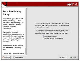 Partitioning Your System If you chose to partition manually, you must tell the installation program where to install Red Hat Enterprise Linux. This is done by defining mount points for one or more disk partitions in which Red Hat Enterprise Linux is installed.
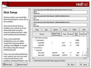
Partition Fields
Recommended Partitioning Scheme
The following is a list of recommendations for partitioning your system: A swap partition (at least 256 MB) — swap partitions are used to support virtual memory. In other words, data is written to a swap partition when there is not enough RAM to store the data your system is processing.
If you are unsure about what size swap partition to create, make it twice the amount of RAM on your machine. It must be of type swap. Creation of the proper amount of swap space varies depending on a number of factors including the following (in descending order of importance): The applications running on the machine. The amount of physical RAM installed on the machine. The version of the OS. Swap should equal 2x physical RAM for up to 2 GB of physical RAM, and then 1x physical RAM for any amount above 2 GB, but never less than 32 MB. Using this formula, a system with 2 GB of physical RAM would have 4 GB of swap, while one with 3 GB of physical RAM would have 5 GB of swap. Creating a large swap space partition can be especially helpful if you plan to upgrade your RAM at a later time. For systems with really large amounts of RAM (more than 32 GB) you can likely get away with a smaller swap partition (around 1x, or less, of physical RAM). A root partition (500 MB - 5.0 GB) — this is where "/" (the root directory) is located. In this setup, all files — except for files stored in /boot (on x86, AMD64, and Intel EM64T) are on the root partition. A 500 MB partition allows you to install a minimal installation; while a 5.0 GB root partition lets you perform a full installation, choosing all package groups. It is recommended that you create a /boot/ partition (100 MB). /boot/ contains the kernels, along with files used during the bootstrap process
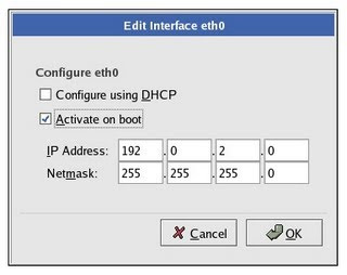 Firewall Configuration
Red Hat Enterprise Linux offers firewall protection for enhanced system security. A firewall exists between your computer and the network, and determines which resources on your computer remote users on the network can access. A properly configured firewall can greatly increase the security of your system.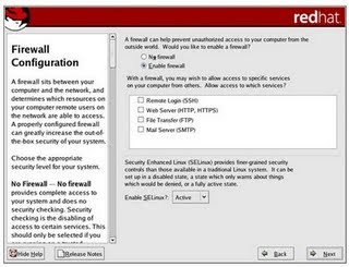
Firewall Configuration
Next, you can decide whether to enable a firewall for your Red Hat Enterprise Linux system. No firewall No firewall provides complete access to your system and does no security checking. Security checking is the disabling of access to certain services. This should only be selected if you are running on a trusted network (not the Internet) or plan to do more firewall configuration later.
Enable firewall
If you choose Enable firewall, connections are not accepted by your systems (other than the default settings) that are not explicitly defined by you. By default, only connections in response to outbound requests, such as DNS replies or DHCP requests are allowed. If access to services running on this machine is needed, you can choose to allow specific services through the firewall.
If you are connecting your system to the Internet, this is the safest option to choose. Next, select which services, if any, should be allowed to pass through the firewall. Enabling these options allow the specified services to pass through the firewall. Note, these services may not be installed on the system by default. Make sure you choose to enable any options that you may need.
Remote Login (SSH)
Secure Shell (SSH) is a suite of tools for logging in to and executing commands on a remote machine. If you plan to use SSH tools to access your machine through a firewall, enable this option. You need to have the openssh-server package installed in order to access your machine remotely, using SSH tools.
Web Server (HTTP, HTTPS)
The HTTP and HTTPS protocols are used by Apache (and by other Web servers) to serve webpages. If you plan on making your Web server publicly available, enable this option. This option is not required for viewing pages locally or for developing webpages. You must install the httpd package if you want to serve webpages.
File Transfer (FTP)
The FTP protocol is used to transfer files between machines on a network. If you plan on making your FTP server publicly available, enable this option. You must install the vsftpd package in order to publicly serve files.
Mail Server (SMTP)
If you want to allow incoming mail delivery through your firewall, so that remote hosts can connect directly to your machine to deliver mail, enable this option. You do not need to enable this if you collect your mail from your Internet Service Provider's server using POP3 or IMAP, or if you use a tool such as fetchmail. Note that an improperly configured SMTP server can allow remote machines to use your server to send spam.
Language Support Selection
You can install and support multiple languages for use on your system. You must select a language to use as the default language. The default language is the language used on the system once the installation is complete. Typically, the default language is the language you selected to use during the installation. If you choose to install other languages during this installation, you can change your default language after the installation. If you are only going to use one language on your system, selecting only that language saves significant disk space.
Caution
If you select only one language, you can only use that specified language after the installation is complete.
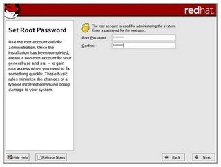
Root Password
Use the root account only for system administration. Create a non-root account for your general use and su - to root when you need to fix something quickly. These basic rules minimize the chances of a typo or an incorrect command doing damage to your system. To become root, type su - at the shell prompt in a terminal window and then press Enter. Then, enter the root password and press Enter.
The installation program prompts you to set a root password for your system. You cannot proceed to the next stage of the installation process without entering a root password The root password must be at least six characters long; the password you type is not echoed to the screen. You must enter the password twice; if the two passwords do not match, the installation program asks you to enter them again.
Tip
To change your root password after you have completed the installation, use the Root Password Tool.
Type the system-config-rootpassword command in a shell prompt to launch the Root Password Tool. If you are not root, it prompts you for the root password to continue. A root password is the administrative password for your Red Hat Enterprise Linux system. You should only log in as root when needed for system maintenance. The root account does not operate within the restrictions placed on normal user accounts, so changes made as root can have implications for your entire system.
Package Group Selection
Now that you have made most of the choices for your installation, you are ready to confirm the default package selection or customize packages for your system.
The Package Installation Defaults screen appears and details the default package set for your Red Hat Enterprise Linux installation. This screen varies depending on the version of Red Hat Enterprise Linux you are installing.
To customize your package set further, select Customize the set of packages to be installed option on the screen. Clicking Next takes you to the Package Group Selection screen. You can select package groups, which group components together according to function (for example, X Window System and Editors), individual packages, or a combination of the two. To select a component, click on the checkbox beside it.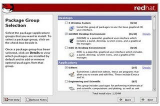
Welcome to Red Hat Enterprise Linux The Welcome screen does not prompt you for any input. Read over the help text in the left panel for additional instructions and information on where to register your Red Hat Enterprise Linux product. Notice the Hide Help button at the bottom left corner of the screen. The help screen is open by default. To minimize the help text, click on Hide Help. Click on the Next button to continue. Language Selection Using your mouse, select a language to use for the installation. Selecting the appropriate language also helps target your time zone configuration later in the installation. The installation program tries to define the appropriate time zone based on what you specify on this screen.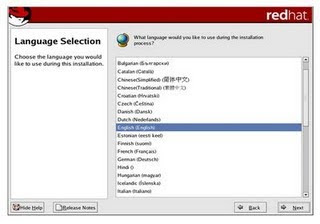
Once you select the appropriate language, click Next to continue.
Disk Partitioning Setup
Partitioning allows you to divide your hard drive into isolated sections, where each section behaves as its own hard drive. Partitioning is particularly useful if you run multiple operating systems.
On this screen, you can choose to perform automatic partitioning, or manual partitioning using Disk Druid.
Automatic partitioning allows you to perform an installation without having to partition your drive(s) yourself. If you do not feel comfortable with partitioning your system, it is recommended that you do not choose to partition manually and instead let the installation program partition for you.
To partition manually, choose the Disk Druid partitioning tool.
Partitioning Your System If you chose to partition manually, you must tell the installation program where to install Red Hat Enterprise Linux. This is done by defining mount points for one or more disk partitions in which Red Hat Enterprise Linux is installed.The partitioning tool used by the installation program is Disk Druid. With the exception of certain esoteric situations, Disk Druid can handle the partitioning requirements for a typical installation.
Disk Druid's Buttons
These buttons control Disk Druid's actions. They are used to change the attributes of a partition (for example the file system type and mount point) and also to create RAID devices. Buttons on this screen are also used to accept the changes you have made, or to exit Disk Druid. For further explanation, take a look at each button in order: Edit: Used to modify attributes of the partition currently selected in the Partitions section. Selecting Edit opens a dialog box. Some or all of the fields can be edited, depending on whether the partition information has already been written to disk. To make a RAID device, you must first create (or reuse existing) software RAID partitions. Once you have created two or more software RAID partitions, select Make RAID to join the software RAID partitions into a RAID device.
These buttons control Disk Druid's actions. They are used to change the attributes of a partition (for example the file system type and mount point) and also to create RAID devices. Buttons on this screen are also used to accept the changes you have made, or to exit Disk Druid. For further explanation, take a look at each button in order: Edit: Used to modify attributes of the partition currently selected in the Partitions section. Selecting Edit opens a dialog box. Some or all of the fields can be edited, depending on whether the partition information has already been written to disk. To make a RAID device, you must first create (or reuse existing) software RAID partitions. Once you have created two or more software RAID partitions, select Make RAID to join the software RAID partitions into a RAID device.
Partition Fields
Above the partition hierarchy are labels which present information about the partitions you are creating. The labels are defined as follows:
Device: This field displays the partition's device name. Mount Point/RAID/Volume: A mount point is the location within the directory hierarchy at which a volume exists; the volume is "mounted" at this location. This field indicates where the partition is mounted. If a partition exists, but is not set, then you need to define its mount point. Double-click on the partition or click the Edit button. Type: This field shows the partition's file system type (for example, ext2 or ext3). Format: This field shows if the partition being created will be formatted. Size (MB): This field shows the partition's size (in MB). Start: This field shows the cylinder on your hard drive where the partition begins. End: This field shows the cylinder on your hard drive where the partition ends.
Device: This field displays the partition's device name. Mount Point/RAID/Volume: A mount point is the location within the directory hierarchy at which a volume exists; the volume is "mounted" at this location. This field indicates where the partition is mounted. If a partition exists, but is not set, then you need to define its mount point. Double-click on the partition or click the Edit button. Type: This field shows the partition's file system type (for example, ext2 or ext3). Format: This field shows if the partition being created will be formatted. Size (MB): This field shows the partition's size (in MB). Start: This field shows the cylinder on your hard drive where the partition begins. End: This field shows the cylinder on your hard drive where the partition ends.
Recommended Partitioning Scheme
The following is a list of recommendations for partitioning your system: A swap partition (at least 256 MB) — swap partitions are used to support virtual memory. In other words, data is written to a swap partition when there is not enough RAM to store the data your system is processing.
If you are unsure about what size swap partition to create, make it twice the amount of RAM on your machine. It must be of type swap. Creation of the proper amount of swap space varies depending on a number of factors including the following (in descending order of importance): The applications running on the machine. The amount of physical RAM installed on the machine. The version of the OS. Swap should equal 2x physical RAM for up to 2 GB of physical RAM, and then 1x physical RAM for any amount above 2 GB, but never less than 32 MB. Using this formula, a system with 2 GB of physical RAM would have 4 GB of swap, while one with 3 GB of physical RAM would have 5 GB of swap. Creating a large swap space partition can be especially helpful if you plan to upgrade your RAM at a later time. For systems with really large amounts of RAM (more than 32 GB) you can likely get away with a smaller swap partition (around 1x, or less, of physical RAM). A root partition (500 MB - 5.0 GB) — this is where "/" (the root directory) is located. In this setup, all files — except for files stored in /boot (on x86, AMD64, and Intel EM64T) are on the root partition. A 500 MB partition allows you to install a minimal installation; while a 5.0 GB root partition lets you perform a full installation, choosing all package groups. It is recommended that you create a /boot/ partition (100 MB). /boot/ contains the kernels, along with files used during the bootstrap process
Network Configuration
If you do not have a network device, this screen does not appear during your installation and you should advance to The installation program automatically detects any network devices you have and displays them in the Network Devices list.
Once you have selected a network device, click Edit. From the Edit Interface pop-up screen, you can choose to configure the IP address and Netmask of the device via DHCP (or manually if DHCP is not selected) and you can choose to activate the device at boot time. If you select Activate on boot, your network interface is started when you boot. If you do not have DHCP client access or you are unsure what to provide here, please contact your network administrator.
If you do not have a network device, this screen does not appear during your installation and you should advance to The installation program automatically detects any network devices you have and displays them in the Network Devices list.
Once you have selected a network device, click Edit. From the Edit Interface pop-up screen, you can choose to configure the IP address and Netmask of the device via DHCP (or manually if DHCP is not selected) and you can choose to activate the device at boot time. If you select Activate on boot, your network interface is started when you boot. If you do not have DHCP client access or you are unsure what to provide here, please contact your network administrator.
Red Hat Enterprise Linux offers firewall protection for enhanced system security. A firewall exists between your computer and the network, and determines which resources on your computer remote users on the network can access. A properly configured firewall can greatly increase the security of your system.
Firewall Configuration
Next, you can decide whether to enable a firewall for your Red Hat Enterprise Linux system. No firewall No firewall provides complete access to your system and does no security checking. Security checking is the disabling of access to certain services. This should only be selected if you are running on a trusted network (not the Internet) or plan to do more firewall configuration later.
Enable firewall
If you choose Enable firewall, connections are not accepted by your systems (other than the default settings) that are not explicitly defined by you. By default, only connections in response to outbound requests, such as DNS replies or DHCP requests are allowed. If access to services running on this machine is needed, you can choose to allow specific services through the firewall.
If you are connecting your system to the Internet, this is the safest option to choose. Next, select which services, if any, should be allowed to pass through the firewall. Enabling these options allow the specified services to pass through the firewall. Note, these services may not be installed on the system by default. Make sure you choose to enable any options that you may need.
Remote Login (SSH)
Secure Shell (SSH) is a suite of tools for logging in to and executing commands on a remote machine. If you plan to use SSH tools to access your machine through a firewall, enable this option. You need to have the openssh-server package installed in order to access your machine remotely, using SSH tools.
Web Server (HTTP, HTTPS)
The HTTP and HTTPS protocols are used by Apache (and by other Web servers) to serve webpages. If you plan on making your Web server publicly available, enable this option. This option is not required for viewing pages locally or for developing webpages. You must install the httpd package if you want to serve webpages.
File Transfer (FTP)
The FTP protocol is used to transfer files between machines on a network. If you plan on making your FTP server publicly available, enable this option. You must install the vsftpd package in order to publicly serve files.
Mail Server (SMTP)
If you want to allow incoming mail delivery through your firewall, so that remote hosts can connect directly to your machine to deliver mail, enable this option. You do not need to enable this if you collect your mail from your Internet Service Provider's server using POP3 or IMAP, or if you use a tool such as fetchmail. Note that an improperly configured SMTP server can allow remote machines to use your server to send spam.
Language Support Selection
You can install and support multiple languages for use on your system. You must select a language to use as the default language. The default language is the language used on the system once the installation is complete. Typically, the default language is the language you selected to use during the installation. If you choose to install other languages during this installation, you can change your default language after the installation. If you are only going to use one language on your system, selecting only that language saves significant disk space.
Caution
If you select only one language, you can only use that specified language after the installation is complete.

Language Support Selection
To use more than one language on your system, choose specific languages to be installed or select all languages to have all available languages installed on your Red Hat Enterprise Linux system. Use the Reset button to cancel your selections. Resetting reverts to the default; only the language you selected for use during the installation is installed. Tip To change the language configuration after you have completed the installation, use the Language Configuration Tool. Type the system-config-language command in a shell prompt to launch the Language Configuration Tool. If you are not root, it prompts you for the root password to continue. Time Zone Configuration Set your time zone by selecting the city closest to your computer's physical location. There are two ways for you to select your time zone: Using your mouse, click on the interactive map to select a specific city (represented by a yellow dot). A red X appears indicating your selection. You can also scroll through the list at the bottom of the screen to select your time zone. Using your mouse, click on a location to highlight your selection
Configuring the Time Zone
Select System Clock uses UTC if you know that your system is set to UTC. To change your time zone configuration after you have completed the installation, use the Time and Date Properties Tool.
Type the system-config-date command in a shell prompt to launch the Time and Date Properties Tool. If you are not root, it prompts you for the root password to continue. To run the Time and Date Properties Tool as a text-based application, use the command timeconfig.
Set Root Password
Setting up a root account and password is one of the most important steps during your installation. Your root account is similar to the administrator account used on Windows NT machines. The root account is used to install packages, upgrade RPMs, and perform most system maintenance. Logging in as root gives you complete control over your system. Note The root user (also known as the superuser) has complete access to the entire system; for this reason, logging in as the root user is best done only to perform system maintenance or administration.
Root Password
Use the root account only for system administration. Create a non-root account for your general use and su - to root when you need to fix something quickly. These basic rules minimize the chances of a typo or an incorrect command doing damage to your system. To become root, type su - at the shell prompt in a terminal window and then press Enter. Then, enter the root password and press Enter.
The installation program prompts you to set a root password for your system. You cannot proceed to the next stage of the installation process without entering a root password The root password must be at least six characters long; the password you type is not echoed to the screen. You must enter the password twice; if the two passwords do not match, the installation program asks you to enter them again.
Tip
To change your root password after you have completed the installation, use the Root Password Tool.
Type the system-config-rootpassword command in a shell prompt to launch the Root Password Tool. If you are not root, it prompts you for the root password to continue. A root password is the administrative password for your Red Hat Enterprise Linux system. You should only log in as root when needed for system maintenance. The root account does not operate within the restrictions placed on normal user accounts, so changes made as root can have implications for your entire system.
Package Group Selection
Now that you have made most of the choices for your installation, you are ready to confirm the default package selection or customize packages for your system.
The Package Installation Defaults screen appears and details the default package set for your Red Hat Enterprise Linux installation. This screen varies depending on the version of Red Hat Enterprise Linux you are installing.
To customize your package set further, select Customize the set of packages to be installed option on the screen. Clicking Next takes you to the Package Group Selection screen. You can select package groups, which group components together according to function (for example, X Window System and Editors), individual packages, or a combination of the two. To select a component, click on the checkbox beside it.
Package Group Selection
Select each component you wish to install. Selecting Everything (at the end of the component list) installs all packages included with Red Hat Enterprise Linux. Once a package group has been selected, click on Details to view which packages are installed by default, and to add or remove optional packages from that group. (Package Group Details)
Preparing to Install
A screen preparing you for the installation of Red Hat Enterprise Linux now appears. For your reference, a complete log of your installation can be found in /root/install.log once you reboot your system.
Warning
If, for some reason, you would rather not continue with the installation process, this is your last opportunity to safely cancel the process and reboot your machine. Once you press the Next button, partitions are written and packages are installed. If you wish to abort the installation, you should reboot now before any existing information on any hard drive is rewritten.
Installing Packages
At this point there is nothing left for you to do until all the packages have been installed. How quickly this happens depends on the number of packages you have selected and your computer's speed.
Installation Complete
Congratulations! Your Red Hat Enterprise Linux installation is now complete! The installation program prompts you to prepare your system for reboot. DOS versus Linux commands
In this appendix, we matched DOS commands with their Linux equivalent. As an extra means of orientation for new users with a Windows background, the table below lists MS-DOS commands with their Linux counterparts. Keep in mind that Linux commands usually have a number of options. Read the Info or man pages on the command to find out more.
BASICS OF NETWORKING
BASICS OF NETWORKING
Networking is connecting two or more devices to allow communication between them with the purpose of sharing information and resources. Examples of these devices are computers, printers, routers, hubs, modems, and PDAs. The information and resources being shared can be anything from MS Office documents and e-mail to printers and fax devices. Internetworking is connecting multiple networks with the purpose of creating one large network. The Internet is the most common example of an internetwork.
Client/server vs Peer-to-peer
Most of today's networks use the client/server model. In this model at least one computer acts as a server. Servers hold resources that are accessed over the network by clients. Examples of resources are shared files, e-mail messages and even applications. Another common server is the print server that allows access to network printers.In a peer-to-peer network model every computer can act as a client and a server at the same time. An example is a network with 4 Windows XP Professional computers in a workgroup using file and print sharing.
LAN/WAN
The terms LAN and WAN mainly refer to the geographical area of the network. LAN is short for Local Area Network and is a high-speed network typically within a building. WAN is short for Wide Area Network and refers to low-speed networks that cover a large distance, for example a network that spans several cities or the entire globe even. The Internet can be considered the largest WAN, but actually consists of many different WANs, which, in turn, include LANs. The connection between LANs in an internetwork is also referred to as a WAN connection, although a network diagram of a WAN often includes the LANs in it.
Private vs Public Networks
Two other terms used to categorize networks are private networks and public networks. A private network is typically within the premises of a corporation and can be accessed only by users working for, or related to, that corporation. A public network Internet can be accessed by multiple individuals and/or corporations, the best example of a public network is again, the Internet.
Media
The physical connection used to transport electrical signals (bits; 1s & 0s) between the network devices is called the media. Examples of network media are copper cabling, fiber optic cabling and infra-red.
Protocols
To be able to communicate with each other, network devices need a common language. The language network devices use is called a protocol. There are many different types of protocols available, and most protocols are actually a suite of several protocols, each with a different function. For example, one protocol allows data transfer between hosts and another can be used to retrieve email from a mail server.
Addressing
If you want to contact somebody by snail-mail or by telephone you need some sort of address. In a telephone network you need to enter a telephone number to reach your intended communication partner. Similar, devices in a network need an address. There are two types of addresses, the first type is configured in software by a network administrator and uses protocols to define the addressing scheme and format, this type is known as network or layer 3 addressing. The other type of address that devices in a network use, is most commonly referred to as MAC address; this address is burned into the chip of the physical network interface.
Network Topologies
A physical topology depicts how network devices are connected physically, the cabling.A logical topology depicts the route a the signal takes on the network. Collisions
A collision indicates that two or more network nodes have tried to access the network simultaneously, and both put a signal on the network cable at the same time which collide with each other. Occasional occurrences are normal and will not affect network performance.
Access Methods
The access method defines how signals are put on the network media.Carrier Sense Multiple Access with Collision Detection (CSMA/CD) The access method used in Ethernet networks. In so called broadcast networks multiple nodes are attached to the same cable segment. To avoid that nodes on the network transmit traffic simultaneously and their signals collide, they listen to the network to sense if it is currently in use. If a collision does occur, it will be detected and the sender will wait for an amount of time determined by a backoff algorithm.
Carrier Sense Multiple Access with Collision Avoidance (CSMA/CA) The access method used in Wireless networks for example. It is similar to CSMA/CD, but CA means that a node broadcasts a warning it is about to use the network, before it actually starts to transmit data. Token Passing This is the access method used in Token Ring and FDDI networks. A token is passed around the network from station to station, when a station does not need to transmit data it passes the token to the next station in the logical ring. A station that receives the token and needs to transmit data seizes the token and sends a data frame, the receiving station marks the data frame as read and passes it forward along the ring to the source station. During this time no other station can transmit data which rules out collisions. The source station releases the token (passing it to the next station) when it receives the data frame and verified it was read.
NETWORK INTERFACE CARDS (NICs)
A Network Interface Card (NIC), typically an expansion card in a computer, is used to connect to the physical network media. Some mainboards and most portable computers are equipped with a built-in (onboard) NIC. NICs are available for different types of network media, the most common today being Ethernet NICs with a RJ-45 socket for UTP/STP cabling. To install a network interface card you need a free ISA or PCI expansion slot and an appropriate driver that the computer's operating system will use to communicate with the NIC. Some older ISA NICs can be manually configured to use a particular IRQ. This is done by setting jumpers or dip switches. Some other NICs allow the IRQ to be configured through the use of configuration software.
Many of today's NICs are equipped with status indicators in the form of leds. These leds can be used to troubleshoot network problems. Typically one green led indicates the NIC is physically connected to the network and flashes when activity occurs, i.e., the port is transmitting or receiving data, this is also known as a heartbeat. When the NIC supports multiple speeds, for example 10 and 100 Mbps, there can be a green led for each speed, of which one is lit indicating the current speed, possibly auto-negotiated with a hub or switch. Some NICs, as well as other network devices such as hubs, include and orange or red led which flashes when collisions occur. If the collision LED flashes repeatedly or continuously, the NIC maybe be configured incorrectly or may be malfunctioning, or there may be other devices utilizing the network heavily.
As described earlier, networks interfaces are physically configured with an address known as the MAC address (MAC is short for Media Access Layer), layer 2 address, Burned In Address (BIA), or physical address. Here's an example of a MAC address: 00-10-E3-42-A8-BC. The first 6 hexadecimal digits specify the vendor/manufacturer of the NIC, the other 6 define the host. MAC addresses are supposedly unique across the planet.
Half duplex vs. Full-duplex communicationHalf-duplex means that only one host can communicate at a given time, two hosts communicating with each other will take turns transmitting. In full-duplex communication both hosts can transmit at the same time, in theory allowing twice as much data to be transmitted over the same connection.The connections able to run at full-duplex are cross-cable connections and connections to a port on a switch, where collisions cannot occur because each end has it's own wire pair (separate segment).
MEDIA
The list below shows some important considerations to make when choosing the proper media for a particular network solution:Cost Besides the high cost of some cable types you also have to consider that the equipment that is used to put the signal on the cable, and take it off the cable, differs a lot in price.Maximum distance Network media is bound to a maximum cable length, because when a signal travels through the cable it will get weaker.
Flexiblity Some types of media are more flexible than others. Typically, the thinner the cable the easier it is to implement. Except for fiber optic cabling, this has to be placed with care to avoid breaks.
Susceptibility to electrical interference Some cables, such as UTP, are more susceptible to nearby high-voltage devices or other sources of electrical interference, than other cables, such as STP or fiber-optics.
Susceptibility to cross-talk Cross-talk refers to interference from other data cables.Susceptibility to fire. Plenum cabling is designed to better withstand the introduction of fire than PVC, and, if burned, generates less smoke toxicity as a result. It is less flexible and it is more expensive. Plenum is typically used in environments such as hospitals.
RS-232
The RS-232 standard specifies serial cabling using DB-9 or DB-25 connectors. The maximum length for a RS-232 cable is 50 feet (15.25 meters) at a baudrate of 19200. The RS-232 standard is designed to supports data transfer rates up to 20 Kbps.
TWISTED PAIR
The most common type of twisted pair cabling is Unshielded Twisted Pair (UTP) cabling. This type of cabling is typically made up of 4 twisted pairs of copper wires as depicted in the image below. Each wire has its own cover, and so does the complete bundle. UTP cabling is categorized using a number. The required category depends on the network technology and the desired transmission speed. Following are the UTP categories:Cat.1 Used for voice/telephone communication only. Cat.2 Data rates up to 4 Mbps.Cat.3 Data rates up to 4 Mbps in TokenRing networks, 10 Mbps in Ethernet networks, bandwidth of 16 MHz.Cat.4 Data rates up to 16 Mbps in TokenRing networks, 10 Mbps in Ethernet networks, bandwidth of 20 MHz.Cat.5 Data rates up to 100 Mbps, bandwidth of 100 MHz Cat.5e Data rates up to 1 Gbps (Gigabit Ethernet), bandwidth of 100 MHz rated (tested up to 350 Mhz).Cat.6 Data rates up to 1 Gbps (Gigabit Ethernet), bandwidth of 250 MHz rated (tested up to 550 Mhz).
10BaseT Ethernet, 100BaseTX Fast Ethernet, 1000BaseT and Token Ring are the most common networks that use twisted pair cabling and are described below.
10BaseTThe 10BaseT specification uses Cat 3, 4 and 5 UTP cabling in a star/hierarchical topology. Devices on the network are connected through a central hub.10BaseT specifications:- Maximum segment length is 100 meters- Maximum data transfer speed is 10Mb/s- Cat 3, 4 and 5 Unshielded Twisted Pair (UTP)
100BaseTX (Fast Ethernet, 802.3u)Is similar to 10BaseT, except it requires at least Category 5 UTP or Category 1 STP cabling. Only uses 4 of the 8 wires like just like 10BaseT. The maximum data transfer rate is 100 Mb/s.
802.5 (Token Ring)Token Ring uses the token passing method described earlier in this TechNote. While the logical topology of a Token Ring network is a ring, the physical topology is star/hierarchical as illustrated in the diagram below. Stations connect to MultiStation Access Units (look a bit like hubs) using UTP cabling which in turn are connected in a physical ring.
Token Ring specifications:- Data transfer rate is 4 or 16 Mb/s- Uses Twisted Pair cabling (Cat 3 for 4 MB/s, Cat 5 for 16 Mb/s)- Logical topology ring, physical topology is star
Token Ring is originally created by IBM, and was later standardized by IEEE under the 802.5 specification. The original IBM Token Ring specification uses IBM Class 1 STP cabling with IBM proprietary connectors. This connector is called the IBM-type Data Connector (IDC) or Universal Data Connector (UDC), and is male nor female.
COAXIALCoaxial cabling is used primarily in 10Base2 (Thinnet) and 10Base5 (Thicknet) Ethernet networks. Coaxial cable uses a copper core with a protective shield, to reduce interference. The shield is covered with the outside cover made from PVC or plenum. The most common types are listed in the following table.RG-58U 50 Ohm, used in 10Base2 Ethernet networks (Thinnet).RG-8 50 Ohm, used in 10Base5 Ethernet networks (Thicknet).RG-59 / RG-6 75 ohms, used for cable television (hence, cable modem access), video, digital audio, and telecommunication applications (for example for E1 coaxial cabling). 10Base2
10Base2 specifications:- Maximum segment length is 185 meters- Maximum data transfer speed is 10Mb/s- 0.2 inch, 50 ohm RG-58 coaxial cable (Thinnet)
10Base5Commonly referred to as Thicknet, commonly uses a bus topology. Stations are attached to the cable using MAUs, a transceiver that is attached to the cable using vampire taps that pierce the cable. A cable with AUI connectors is used to connect the transceiver to the network interface on for example a computer, hub or repeater. Both cable ends are terminated using a 50 ohm terminator. 10Base5 specifications:- Maximum segment length is 500 meters - Maximum data transfer speed is 10Mb/s- 0.4 inch, 50 ohm coaxial RG-8 cabling (Thicknet)
FIBER OPTICFiber optic cabling is a rather new technology that allows for fast data transfer over large distances. Fiber optic cabling is not susceptible to electrical interference, but needs expensive equipment and is fragile. There are two main types of fiber optics, the first is multi-mode, which is typically used in corporate networks' backbone. In a multi-mode cable, light travels down the fiber cable in multiple paths. Essentially, the light beam is reflected off the cladding (material surrounding the actual fiber) as it travels down the core. The other type is single-mode, this type is typically used by telephone companies to cover very large distances. In a single-mode cable, light travels thru the cable without interacting with the glass cladding (material surrounding the actual fiber), maintaining signal quality for great distances.
Fiber optic cabling is connected using SC, ST or MIC connectors.Network technologies that use fiber optic cabling include 100BasesFX and FDDI.
100BaseFX (802.3u)Similar to 100BaseTX but designed to operate over 2 strands of single-mode or multi-mode fiber cabling. One cable is used to send the other is used for collision detection and receiving. The maximum length of a 100BaseFX link is 400 meters in half-duplex mode, 2000 meters in full-duplex mode.
- 1000BaseLX, uses multi-mode fiber with a maximum length of 550 meters or single-mode fiber with a maximum length of 5 km- 1000BaseSX, uses multi-mode fiber with a maximum length of 500 meters
FDDI
Another token-passing network technology is Fiber Distributed Data Interface. FDDI networks are often used as backbones for wide-area networks providing data transfer rates up to 100 Mb/s using fiber media. The use of fiber makes it immune to electrical interference, and allows it to transmit data over greater distances. FDDI provides fault tolerance by using a dual counter-rotating ring configuration, an active primary ring and a secondary ring used for backup.
WIRELESS
InfraredInfrared (IR) communication is typically used between devices such as PDAs, laptops and printers. An advantage of IR communication is that it is not susceptible to electrical interference. The main disadvantage, besides the rather short maximum supported distance between devices, is that there must be a clear path between the devices. Supports data transfer rates up to 4 Mbps.
802.11b (Wi-fi)
The 802.11b standard specifies wireless Ethernet LAN technology. The topology used in wireless networks is known as cellular. It is a wireless structure where stations send signals to each other via wireless media hubs. The access method for 802.11b is CSMA/CA. Clients connect via wireless access points with data transfer rates up to 11 Mbps. 802.11b operates in the 2.4 GHz range. Another WLAN standard that has recently emerged, 802.11a, offers a maximum transmission speed of 54 Mbps at 5 GHz frequency.
NETWORK COMPONENTS
Repeaters Used to extend the maximum distance a cable segment can span. Repeaters grab the incoming electrical signal from the cable, amplify it, and send it out.Hubs Hubs, also known as concentrators or multiport repeaters, are used in star/hierarchical networks to connect multiple stations/cable segments. There are two main types of hubs: passive and active. An active hub takes the incoming frames, amplifies the signal, and forwards it to all other ports, a passive hub simply splits the signal and forwards it.Bridges Used to increase network performance by segmenting networks in separate collision domains, or increase the network size. Bridges are not aware of upper-layer protocols such as TCP/IP or IPX/SPX. They keep a table with MAC addresses of all nodes, and on which segment they are located.
Switches Similar to bridges; they also keep a table with MAC addresses per port to make switching decisions. The main difference is that a switch has more ports than a bridge, and instead of interconnecting networks it is typically used to connect hosts and servers like a hub does, but offers dedicated bandwidth per port, hence offers much higher network performance than hubs.
Routers Routers are used to interconnect multiple (sub-)networks and route information between these networks by choosing an optimal path ("route") to the destination based on addressing information from protocols such as TCP/IP or IPX/SPX. Router are also typically used to connect a LAN to a WAN or another LAN, which can use different technologies such as Token Ring, Ethernet, ISDN, Frame Relay etc.
Gateways Used to connect networks with dissimilar technologies, for example a Microsoft TCP/IP network and NetWare IPX/SPX network can be connected using a gateway. Typically implemented in software on a router.Firewalls Protects a private network from external users, typically those from the Internet, by hiding the internal network and filtering incoming packets. A firewall is not always a hardware device, it can be implemented in software on a router or proxy server as well.
PROTOCOLS
TCP/IP
TCP/IP is today's most popular network protocol and is the protocol in the Internet. It is a routable protocol that provides connection between heterogeneous systems, these are the main reasons the protocol is so widely adapted; for example it allows communication between UNIX, Windows, Netware and Mac OS computers spread over multiple interconnected networks. The "TCP/IP protocol" is actually the "TCP/IP suite" composed of many different protocols each with its own functions. The two main protocols are in its name: the Internet Protocol and the Transmission Control Protocol.
IP addressing is assigning a 32-bit logical numeric address to a network device. Every IP address on the network must be unique. An IP address is represented in a dotted decimal format, for example: 159.101.6.8. As you can see the address is divided in 4 parts, these parts are called octets. The current used addressing schema in version 4 of IP is divided in 5 Classes:Classes First OctetClass A 1 126Class B 128 191Class C 192 223Class D 224 239Class E 240 254
A subnet mask is used to determine which part is the network part and which is the host part.Default subnet masks:Class A 255.0.0.0Class B 255.255.0.0Class C 255.255.255.0
IANA reserved 4 address ranges to be used in private networks, these addresses won't appear on the Internet avoiding IP address conflicts:- 10.0.0.0 through 10.255.255.255- 172.16.0.0 through 172.31.255.255- 192.168.0.0 through 192.168.255.255- 169.254.0.1 through 169.254.255.254 (reserved for Automatic Private IP Addressing)
IPX/SPXAlthough current versions of Novell Netware use TCP/IP, before Netware version 5, IPX was the protocol in Netware networks. It is a small and easy to implement routable protocol developed by Novell and based on the Xerox Network System. The Netware protocol suite is a suite of several protocols for different functions, the most important being IPX and SPX. IPX is similar to the Internet Protocol from the TCP/IP suite, it is a connectionless Layer 3 (Network layer) protocol used to transfer datagrams between hosts and networks. SPX is the Transport protocol used to provide reliable transport for IPX datagrams, similar as TCP does for IP.
The frame types of two Netware hosts must match to enable communication without a router. IPX can use several frame formats, of which the two most important are listed in the following table.Frame Format Frame Type Netware VersionsNovell 802.3 raw 802.3 Default frame type for Netware 3.11 and earlier. Supports only IPX/SPX as the upper layer protocolIEEE 802.3 802.2 Default frame type for Netware 3.12 and 4.x. The main difference with Novell's 802.3 format is the addition of LLC field, which specifies the upper-layer protocol, such as IPX or IP.
An complete IPX network address is 80 bits in length and is represented in a hexadecimal format. As with all routable protocols it needs a network and a host portion, the network portion is 32 bits in length and is manually configured. The host portion is 48 bits in length and is derived from the MAC address of the host's network interface.
Examples of complete IPX internetwork addresses are:- 0CC001D8.0050.BF61.6C71- 0000ABBA.0060.9736.954B- 00000046.0060.E92A.C2A4
NWLINK is Microsoft's implementation of IPX/SPX which allows Windows clients to communicate with Netware servers.
AppleTalkAppleTalk was developed by Apple Computers in the early 1980s to allow file and printer sharing and mail functionality between Macintosh computers. A Mac that shares resources is called a server, and the computer connecting to it a client. Like TCP/IP, AppleTalk is not just one protocol, but a suite of several protocols for different functions. It is built-in in every Macintosh computer and requires virtually no user interaction, therefore it is very easy to administer in small network environments. Address assignment in AppleTalk networks is automatically. Besides Ethernet and TokenRing, AppleTalk can also be used on Apple's own network technology called LocalTalk, which uses UTP/STP cabling.
NetBEUI/NETBIOS
NETBios Extended User Interface is a non-routable Transport layer protocol. The reason it is non-routable is in its flat addressing schema, NETBEUI uses Netbios names to identify computers on the network that do not contain a network portion. Netbios names are sometimes referred to as friendly names. NetBIOS names are 16 characters in length and cannot contain any of the the following characters: \ / : * ? " < > The first 15 characters represents a unique name identifying a resource, the 16th character (if you would set a name of 8 characters it is padded with spaces up to 15 characters long to allow a '16th' character) is a suffix identifying the type of resource or group of resources. For example the redirector, server, or messenger services can be installed on one computer resulting in three times the same name but with different suffixes.
NETBEUI is a broadcast protocol, meaning a computer running NETBEUI discovers the MAC address from the intended communication partner by sending out a broadcast with the NETBIOS name. The main advantage of NETBEUI is that it is small in size and easy-configurable.
Networking is connecting two or more devices to allow communication between them with the purpose of sharing information and resources. Examples of these devices are computers, printers, routers, hubs, modems, and PDAs. The information and resources being shared can be anything from MS Office documents and e-mail to printers and fax devices. Internetworking is connecting multiple networks with the purpose of creating one large network. The Internet is the most common example of an internetwork.
Client/server vs Peer-to-peer
Most of today's networks use the client/server model. In this model at least one computer acts as a server. Servers hold resources that are accessed over the network by clients. Examples of resources are shared files, e-mail messages and even applications. Another common server is the print server that allows access to network printers.In a peer-to-peer network model every computer can act as a client and a server at the same time. An example is a network with 4 Windows XP Professional computers in a workgroup using file and print sharing.
LAN/WAN
The terms LAN and WAN mainly refer to the geographical area of the network. LAN is short for Local Area Network and is a high-speed network typically within a building. WAN is short for Wide Area Network and refers to low-speed networks that cover a large distance, for example a network that spans several cities or the entire globe even. The Internet can be considered the largest WAN, but actually consists of many different WANs, which, in turn, include LANs. The connection between LANs in an internetwork is also referred to as a WAN connection, although a network diagram of a WAN often includes the LANs in it.
Private vs Public Networks
Two other terms used to categorize networks are private networks and public networks. A private network is typically within the premises of a corporation and can be accessed only by users working for, or related to, that corporation. A public network Internet can be accessed by multiple individuals and/or corporations, the best example of a public network is again, the Internet.
Media
The physical connection used to transport electrical signals (bits; 1s & 0s) between the network devices is called the media. Examples of network media are copper cabling, fiber optic cabling and infra-red.
Protocols
To be able to communicate with each other, network devices need a common language. The language network devices use is called a protocol. There are many different types of protocols available, and most protocols are actually a suite of several protocols, each with a different function. For example, one protocol allows data transfer between hosts and another can be used to retrieve email from a mail server.
Addressing
If you want to contact somebody by snail-mail or by telephone you need some sort of address. In a telephone network you need to enter a telephone number to reach your intended communication partner. Similar, devices in a network need an address. There are two types of addresses, the first type is configured in software by a network administrator and uses protocols to define the addressing scheme and format, this type is known as network or layer 3 addressing. The other type of address that devices in a network use, is most commonly referred to as MAC address; this address is burned into the chip of the physical network interface.
Network Topologies
A physical topology depicts how network devices are connected physically, the cabling.A logical topology depicts the route a the signal takes on the network. Collisions
A collision indicates that two or more network nodes have tried to access the network simultaneously, and both put a signal on the network cable at the same time which collide with each other. Occasional occurrences are normal and will not affect network performance.
Access Methods
The access method defines how signals are put on the network media.Carrier Sense Multiple Access with Collision Detection (CSMA/CD) The access method used in Ethernet networks. In so called broadcast networks multiple nodes are attached to the same cable segment. To avoid that nodes on the network transmit traffic simultaneously and their signals collide, they listen to the network to sense if it is currently in use. If a collision does occur, it will be detected and the sender will wait for an amount of time determined by a backoff algorithm.
Carrier Sense Multiple Access with Collision Avoidance (CSMA/CA) The access method used in Wireless networks for example. It is similar to CSMA/CD, but CA means that a node broadcasts a warning it is about to use the network, before it actually starts to transmit data. Token Passing This is the access method used in Token Ring and FDDI networks. A token is passed around the network from station to station, when a station does not need to transmit data it passes the token to the next station in the logical ring. A station that receives the token and needs to transmit data seizes the token and sends a data frame, the receiving station marks the data frame as read and passes it forward along the ring to the source station. During this time no other station can transmit data which rules out collisions. The source station releases the token (passing it to the next station) when it receives the data frame and verified it was read.
NETWORK INTERFACE CARDS (NICs)
A Network Interface Card (NIC), typically an expansion card in a computer, is used to connect to the physical network media. Some mainboards and most portable computers are equipped with a built-in (onboard) NIC. NICs are available for different types of network media, the most common today being Ethernet NICs with a RJ-45 socket for UTP/STP cabling. To install a network interface card you need a free ISA or PCI expansion slot and an appropriate driver that the computer's operating system will use to communicate with the NIC. Some older ISA NICs can be manually configured to use a particular IRQ. This is done by setting jumpers or dip switches. Some other NICs allow the IRQ to be configured through the use of configuration software.
Many of today's NICs are equipped with status indicators in the form of leds. These leds can be used to troubleshoot network problems. Typically one green led indicates the NIC is physically connected to the network and flashes when activity occurs, i.e., the port is transmitting or receiving data, this is also known as a heartbeat. When the NIC supports multiple speeds, for example 10 and 100 Mbps, there can be a green led for each speed, of which one is lit indicating the current speed, possibly auto-negotiated with a hub or switch. Some NICs, as well as other network devices such as hubs, include and orange or red led which flashes when collisions occur. If the collision LED flashes repeatedly or continuously, the NIC maybe be configured incorrectly or may be malfunctioning, or there may be other devices utilizing the network heavily.
As described earlier, networks interfaces are physically configured with an address known as the MAC address (MAC is short for Media Access Layer), layer 2 address, Burned In Address (BIA), or physical address. Here's an example of a MAC address: 00-10-E3-42-A8-BC. The first 6 hexadecimal digits specify the vendor/manufacturer of the NIC, the other 6 define the host. MAC addresses are supposedly unique across the planet.
Half duplex vs. Full-duplex communicationHalf-duplex means that only one host can communicate at a given time, two hosts communicating with each other will take turns transmitting. In full-duplex communication both hosts can transmit at the same time, in theory allowing twice as much data to be transmitted over the same connection.The connections able to run at full-duplex are cross-cable connections and connections to a port on a switch, where collisions cannot occur because each end has it's own wire pair (separate segment).
MEDIA
The list below shows some important considerations to make when choosing the proper media for a particular network solution:Cost Besides the high cost of some cable types you also have to consider that the equipment that is used to put the signal on the cable, and take it off the cable, differs a lot in price.Maximum distance Network media is bound to a maximum cable length, because when a signal travels through the cable it will get weaker.
Flexiblity Some types of media are more flexible than others. Typically, the thinner the cable the easier it is to implement. Except for fiber optic cabling, this has to be placed with care to avoid breaks.
Susceptibility to electrical interference Some cables, such as UTP, are more susceptible to nearby high-voltage devices or other sources of electrical interference, than other cables, such as STP or fiber-optics.
Susceptibility to cross-talk Cross-talk refers to interference from other data cables.Susceptibility to fire. Plenum cabling is designed to better withstand the introduction of fire than PVC, and, if burned, generates less smoke toxicity as a result. It is less flexible and it is more expensive. Plenum is typically used in environments such as hospitals.
RS-232
The RS-232 standard specifies serial cabling using DB-9 or DB-25 connectors. The maximum length for a RS-232 cable is 50 feet (15.25 meters) at a baudrate of 19200. The RS-232 standard is designed to supports data transfer rates up to 20 Kbps.
TWISTED PAIR
The most common type of twisted pair cabling is Unshielded Twisted Pair (UTP) cabling. This type of cabling is typically made up of 4 twisted pairs of copper wires as depicted in the image below. Each wire has its own cover, and so does the complete bundle. UTP cabling is categorized using a number. The required category depends on the network technology and the desired transmission speed. Following are the UTP categories:Cat.1 Used for voice/telephone communication only. Cat.2 Data rates up to 4 Mbps.Cat.3 Data rates up to 4 Mbps in TokenRing networks, 10 Mbps in Ethernet networks, bandwidth of 16 MHz.Cat.4 Data rates up to 16 Mbps in TokenRing networks, 10 Mbps in Ethernet networks, bandwidth of 20 MHz.Cat.5 Data rates up to 100 Mbps, bandwidth of 100 MHz Cat.5e Data rates up to 1 Gbps (Gigabit Ethernet), bandwidth of 100 MHz rated (tested up to 350 Mhz).Cat.6 Data rates up to 1 Gbps (Gigabit Ethernet), bandwidth of 250 MHz rated (tested up to 550 Mhz).
10BaseT Ethernet, 100BaseTX Fast Ethernet, 1000BaseT and Token Ring are the most common networks that use twisted pair cabling and are described below.
10BaseTThe 10BaseT specification uses Cat 3, 4 and 5 UTP cabling in a star/hierarchical topology. Devices on the network are connected through a central hub.10BaseT specifications:- Maximum segment length is 100 meters- Maximum data transfer speed is 10Mb/s- Cat 3, 4 and 5 Unshielded Twisted Pair (UTP)
100BaseTX (Fast Ethernet, 802.3u)Is similar to 10BaseT, except it requires at least Category 5 UTP or Category 1 STP cabling. Only uses 4 of the 8 wires like just like 10BaseT. The maximum data transfer rate is 100 Mb/s.
802.5 (Token Ring)Token Ring uses the token passing method described earlier in this TechNote. While the logical topology of a Token Ring network is a ring, the physical topology is star/hierarchical as illustrated in the diagram below. Stations connect to MultiStation Access Units (look a bit like hubs) using UTP cabling which in turn are connected in a physical ring.
Token Ring specifications:- Data transfer rate is 4 or 16 Mb/s- Uses Twisted Pair cabling (Cat 3 for 4 MB/s, Cat 5 for 16 Mb/s)- Logical topology ring, physical topology is star
Token Ring is originally created by IBM, and was later standardized by IEEE under the 802.5 specification. The original IBM Token Ring specification uses IBM Class 1 STP cabling with IBM proprietary connectors. This connector is called the IBM-type Data Connector (IDC) or Universal Data Connector (UDC), and is male nor female.
COAXIALCoaxial cabling is used primarily in 10Base2 (Thinnet) and 10Base5 (Thicknet) Ethernet networks. Coaxial cable uses a copper core with a protective shield, to reduce interference. The shield is covered with the outside cover made from PVC or plenum. The most common types are listed in the following table.RG-58U 50 Ohm, used in 10Base2 Ethernet networks (Thinnet).RG-8 50 Ohm, used in 10Base5 Ethernet networks (Thicknet).RG-59 / RG-6 75 ohms, used for cable television (hence, cable modem access), video, digital audio, and telecommunication applications (for example for E1 coaxial cabling). 10Base2
10Base2 specifications:- Maximum segment length is 185 meters- Maximum data transfer speed is 10Mb/s- 0.2 inch, 50 ohm RG-58 coaxial cable (Thinnet)
10Base5Commonly referred to as Thicknet, commonly uses a bus topology. Stations are attached to the cable using MAUs, a transceiver that is attached to the cable using vampire taps that pierce the cable. A cable with AUI connectors is used to connect the transceiver to the network interface on for example a computer, hub or repeater. Both cable ends are terminated using a 50 ohm terminator. 10Base5 specifications:- Maximum segment length is 500 meters - Maximum data transfer speed is 10Mb/s- 0.4 inch, 50 ohm coaxial RG-8 cabling (Thicknet)
FIBER OPTICFiber optic cabling is a rather new technology that allows for fast data transfer over large distances. Fiber optic cabling is not susceptible to electrical interference, but needs expensive equipment and is fragile. There are two main types of fiber optics, the first is multi-mode, which is typically used in corporate networks' backbone. In a multi-mode cable, light travels down the fiber cable in multiple paths. Essentially, the light beam is reflected off the cladding (material surrounding the actual fiber) as it travels down the core. The other type is single-mode, this type is typically used by telephone companies to cover very large distances. In a single-mode cable, light travels thru the cable without interacting with the glass cladding (material surrounding the actual fiber), maintaining signal quality for great distances.
Fiber optic cabling is connected using SC, ST or MIC connectors.Network technologies that use fiber optic cabling include 100BasesFX and FDDI.
100BaseFX (802.3u)Similar to 100BaseTX but designed to operate over 2 strands of single-mode or multi-mode fiber cabling. One cable is used to send the other is used for collision detection and receiving. The maximum length of a 100BaseFX link is 400 meters in half-duplex mode, 2000 meters in full-duplex mode.
- 1000BaseLX, uses multi-mode fiber with a maximum length of 550 meters or single-mode fiber with a maximum length of 5 km- 1000BaseSX, uses multi-mode fiber with a maximum length of 500 meters
FDDI
Another token-passing network technology is Fiber Distributed Data Interface. FDDI networks are often used as backbones for wide-area networks providing data transfer rates up to 100 Mb/s using fiber media. The use of fiber makes it immune to electrical interference, and allows it to transmit data over greater distances. FDDI provides fault tolerance by using a dual counter-rotating ring configuration, an active primary ring and a secondary ring used for backup.
WIRELESS
InfraredInfrared (IR) communication is typically used between devices such as PDAs, laptops and printers. An advantage of IR communication is that it is not susceptible to electrical interference. The main disadvantage, besides the rather short maximum supported distance between devices, is that there must be a clear path between the devices. Supports data transfer rates up to 4 Mbps.
802.11b (Wi-fi)
The 802.11b standard specifies wireless Ethernet LAN technology. The topology used in wireless networks is known as cellular. It is a wireless structure where stations send signals to each other via wireless media hubs. The access method for 802.11b is CSMA/CA. Clients connect via wireless access points with data transfer rates up to 11 Mbps. 802.11b operates in the 2.4 GHz range. Another WLAN standard that has recently emerged, 802.11a, offers a maximum transmission speed of 54 Mbps at 5 GHz frequency.
NETWORK COMPONENTS
Repeaters Used to extend the maximum distance a cable segment can span. Repeaters grab the incoming electrical signal from the cable, amplify it, and send it out.Hubs Hubs, also known as concentrators or multiport repeaters, are used in star/hierarchical networks to connect multiple stations/cable segments. There are two main types of hubs: passive and active. An active hub takes the incoming frames, amplifies the signal, and forwards it to all other ports, a passive hub simply splits the signal and forwards it.Bridges Used to increase network performance by segmenting networks in separate collision domains, or increase the network size. Bridges are not aware of upper-layer protocols such as TCP/IP or IPX/SPX. They keep a table with MAC addresses of all nodes, and on which segment they are located.
Switches Similar to bridges; they also keep a table with MAC addresses per port to make switching decisions. The main difference is that a switch has more ports than a bridge, and instead of interconnecting networks it is typically used to connect hosts and servers like a hub does, but offers dedicated bandwidth per port, hence offers much higher network performance than hubs.
Routers Routers are used to interconnect multiple (sub-)networks and route information between these networks by choosing an optimal path ("route") to the destination based on addressing information from protocols such as TCP/IP or IPX/SPX. Router are also typically used to connect a LAN to a WAN or another LAN, which can use different technologies such as Token Ring, Ethernet, ISDN, Frame Relay etc.
Gateways Used to connect networks with dissimilar technologies, for example a Microsoft TCP/IP network and NetWare IPX/SPX network can be connected using a gateway. Typically implemented in software on a router.Firewalls Protects a private network from external users, typically those from the Internet, by hiding the internal network and filtering incoming packets. A firewall is not always a hardware device, it can be implemented in software on a router or proxy server as well.
PROTOCOLS
TCP/IP
TCP/IP is today's most popular network protocol and is the protocol in the Internet. It is a routable protocol that provides connection between heterogeneous systems, these are the main reasons the protocol is so widely adapted; for example it allows communication between UNIX, Windows, Netware and Mac OS computers spread over multiple interconnected networks. The "TCP/IP protocol" is actually the "TCP/IP suite" composed of many different protocols each with its own functions. The two main protocols are in its name: the Internet Protocol and the Transmission Control Protocol.
IP addressing is assigning a 32-bit logical numeric address to a network device. Every IP address on the network must be unique. An IP address is represented in a dotted decimal format, for example: 159.101.6.8. As you can see the address is divided in 4 parts, these parts are called octets. The current used addressing schema in version 4 of IP is divided in 5 Classes:Classes First OctetClass A 1 126Class B 128 191Class C 192 223Class D 224 239Class E 240 254
A subnet mask is used to determine which part is the network part and which is the host part.Default subnet masks:Class A 255.0.0.0Class B 255.255.0.0Class C 255.255.255.0
IANA reserved 4 address ranges to be used in private networks, these addresses won't appear on the Internet avoiding IP address conflicts:- 10.0.0.0 through 10.255.255.255- 172.16.0.0 through 172.31.255.255- 192.168.0.0 through 192.168.255.255- 169.254.0.1 through 169.254.255.254 (reserved for Automatic Private IP Addressing)
IPX/SPXAlthough current versions of Novell Netware use TCP/IP, before Netware version 5, IPX was the protocol in Netware networks. It is a small and easy to implement routable protocol developed by Novell and based on the Xerox Network System. The Netware protocol suite is a suite of several protocols for different functions, the most important being IPX and SPX. IPX is similar to the Internet Protocol from the TCP/IP suite, it is a connectionless Layer 3 (Network layer) protocol used to transfer datagrams between hosts and networks. SPX is the Transport protocol used to provide reliable transport for IPX datagrams, similar as TCP does for IP.
The frame types of two Netware hosts must match to enable communication without a router. IPX can use several frame formats, of which the two most important are listed in the following table.Frame Format Frame Type Netware VersionsNovell 802.3 raw 802.3 Default frame type for Netware 3.11 and earlier. Supports only IPX/SPX as the upper layer protocolIEEE 802.3 802.2 Default frame type for Netware 3.12 and 4.x. The main difference with Novell's 802.3 format is the addition of LLC field, which specifies the upper-layer protocol, such as IPX or IP.
An complete IPX network address is 80 bits in length and is represented in a hexadecimal format. As with all routable protocols it needs a network and a host portion, the network portion is 32 bits in length and is manually configured. The host portion is 48 bits in length and is derived from the MAC address of the host's network interface.
Examples of complete IPX internetwork addresses are:- 0CC001D8.0050.BF61.6C71- 0000ABBA.0060.9736.954B- 00000046.0060.E92A.C2A4
NWLINK is Microsoft's implementation of IPX/SPX which allows Windows clients to communicate with Netware servers.
AppleTalkAppleTalk was developed by Apple Computers in the early 1980s to allow file and printer sharing and mail functionality between Macintosh computers. A Mac that shares resources is called a server, and the computer connecting to it a client. Like TCP/IP, AppleTalk is not just one protocol, but a suite of several protocols for different functions. It is built-in in every Macintosh computer and requires virtually no user interaction, therefore it is very easy to administer in small network environments. Address assignment in AppleTalk networks is automatically. Besides Ethernet and TokenRing, AppleTalk can also be used on Apple's own network technology called LocalTalk, which uses UTP/STP cabling.
NetBEUI/NETBIOS
NETBios Extended User Interface is a non-routable Transport layer protocol. The reason it is non-routable is in its flat addressing schema, NETBEUI uses Netbios names to identify computers on the network that do not contain a network portion. Netbios names are sometimes referred to as friendly names. NetBIOS names are 16 characters in length and cannot contain any of the the following characters: \ / : * ? " < > The first 15 characters represents a unique name identifying a resource, the 16th character (if you would set a name of 8 characters it is padded with spaces up to 15 characters long to allow a '16th' character) is a suffix identifying the type of resource or group of resources. For example the redirector, server, or messenger services can be installed on one computer resulting in three times the same name but with different suffixes.
NETBEUI is a broadcast protocol, meaning a computer running NETBEUI discovers the MAC address from the intended communication partner by sending out a broadcast with the NETBIOS name. The main advantage of NETBEUI is that it is small in size and easy-configurable.
Subscribe to:
Posts (Atom)